


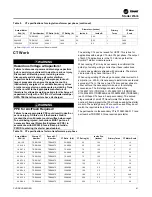


Starter Work
44
CVRF-SVN005C-EN
Potential Transformers, Optional
PTs
WARNING
Hazardous Voltage w/Capacitors!
Failure to disconnect power and discharge capacitors
before servicing could result in death or serious injury.
Disconnect all electric power, including remote
disconnects and discharge all motor start/run
capacitors before servicing. Follow proper lockout/
tagout procedures to ensure the power cannot be
inadvertently energized. For variable frequency drives
or other energy storing components provided by Trane
or others, refer to the appropriate manufacturer’s
literature for allowable waiting periods for discharge of
capacitors. Verify with a CAT III or IV voltmeter rated per
NFPA 70E that all capacitors have discharged.
WARNING
PPE for Arc/Flash Required!
Failure to wear appropriate PPE could result in death or
serious injury. On this unit, if the handle shield is
cracked the circuit breaker could arc/flash when reset.
To avoid being injured, technicians MUST put on all
necessary Personal Protective Equipment (PPE), in
accordance with NFPA70E for arc/flash protection,
PRIOR to entering the starter panel cabinet.
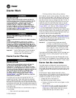
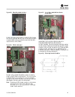
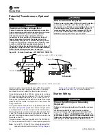
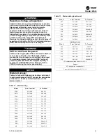
Figure 58. Potential transformer, X13590079-01, TRR00713
Install the optional potential transformers (PTs). The potential
transformers are used to measure line voltage. The wiring
must have the correct polarity for them to work correctly.
For applications greater than 600 Vac, a large medium voltage
PT is used to step from line voltage to 115 Vac and a second
PT steps the voltage to less than 30 Vac. The large PT is a
three phase type except for the 6600 Vac where three single
phase PTs are used. Refer to CVRD-SVN11*-EN, for detailed
wiring instructions.
For applications less than 600 Vac a single PT per phase like
that shown in
is used to step the signal down
to a voltage less than 30 Vac for input into the starter module.
The black leads are connected to the line from phases A-B, B-
C and C-A. The green ground wire is connected to chassis
ground. Field provided wires connect the Starter module to the
terminals on the PTs.
The part number on the less than 600 volt PT is X13590079-
01, Trane part number TRR00713, three required per starter.
Note:
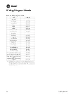
Fuses (2F1, 2F2 and 2F3) must be installed with the
optional potential transformers (see
for a list of the appropriate wiring diagram
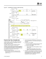
examples). Use
Starter Wiring
WARNING
Proper Field Wiring and Grounding
Required!
Failure to follow code could result in death or serious
injury.
All field wiring MUST be performed by qualified
personnel. Improperly installed and grounded field
wiring poses FIRE and ELECTROCUTION hazards. To
avoid these hazards, you MUST follow requirements for
field wiring installation and grounding as described in
NEC and your local/state/national electrical codes.
Schematic
Secondary Leads, 0.187 in. terminals
Top View
Primary Leads, 0.250 in. terminals
Polarity Dots
Secondary
Primary
Polarity Dots
Содержание Symbio CVRF
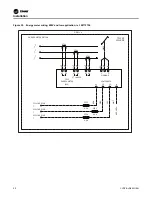
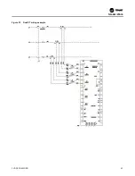
Страница 43: ...Figure 57 Dual CT wiring example Starter Work CVRF SVN005C EN 43...
Страница 47: ...Notes CVRF SVN005C EN 47...