9
4. Assembly and
Installation
4.1 Break Point and General
Unit Assembly
Instructions
Ensure that all the air-handling unit
sections are positioned in the correct
order.
Each section will display a unit drawing
with its position OUTLINED.
1.Each of the unit sections should be
placed on a level foundation and within
200 mm of its adjoining section.
2.Remove any supports and bracing
which are supplied with the unit for
transport. All such supports will be
clearly marked:
“FOR TRANSPORT ONLY –
REMOVE BEFORE ASSEMBLY”
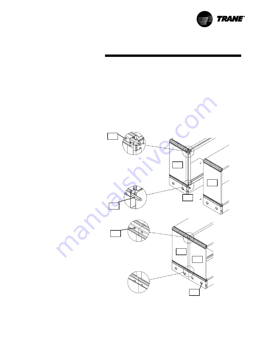
3.Remove 4 M6 fixing
bolts (A)
from the
protruding portion of the 4 framework
joining bars (see Figure 9), then loosen
the remaining 4 bolts that are located
on the fixed side of the break point
joining bars.
Pull together the sections of the unit,
ensuring that the joiner bar in each of
the 4 corners is fitted into its adjoining
section and the plastic “T” section
sealing strip locates over the adjoining
panel.
The 52-mm diameter holes provided in
the unit base frame should be used to
manoeuvre the sections together.
Greased skid plates will greatly assist
the whole assembly operation.
4. Secure the break point joint externally
by replacing the 4 M6 bolts and
washers, which were previously
removed in step (3). Retighten the 8
bolts located on both sides of the break
point joint.
Where applicable, complete the
assembly of the unit as follows:
4.1.3. Fan sections
Bolt the outlet of the fan to the flexible
connection using the M8 bolts provided.
4.1.4. Damper sections
Pop-rivet through the damper spigot and
the adjoining plastic “J” section into the
adjacent fixed panel using 5-mm-
diameter rivets.
4.1.5. Coil sections (with drip pans)
Fix through the top of the drip pan into the
box section using the self-drilling screws,
which are provided. Then seal along all
joints with a waterproof “silicone” based
sealant. We recommend “Siloflex.”
4.1.6. Weatherproof roofs
Slide on the “Doby” cleats, which are
provided, and then fix in position at the
ends with the cleat clips on the roof return
edge using 5mm diameter rivets.
2
1
2
1
CLCH-SVX05A-GB
Figure 9
Figure Notes:
1. Part 1
2.Part 2
3. Break Point
4. Bolts “A”
5. Fixed bolts
6. 52 mm diameter holes
7. 8 x M6 bolts (2 per join)
1
2
5
4
7
6
1
2
3


