CGAD-SVN02C-EN
81
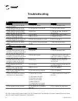
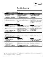
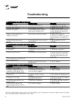
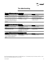
Troubleshooting
Note: These troubleshooting procedures apply to the CGAD Standard units. Troubleshooting with optional components should be checked
with the Technical Assistance Department at Trane do Brasil.
Symptoms
Possible Cause
Procedure
1. High air temperature through the
condenser.
1. Reduced air flow through the
condenser.
1. Readjust the flow. Check for
obstructions.
2. The air leaving the condenser is
too cold. Small temperature increase
through the condenser.
2. The condenser vanes are dirty.
2. Clean the vanes.
3. The air leaving the condenser is
too hot.
3. Poor operation of the condenser
fans.
3. Check the motors of the
condenser fans.
4. The condenser is unusually hot
and the discharge pressure is too
high.
4. Non-condensable air or gases in
the systems.
4. Transfer the refrigerant to the
recycling. Make a new vacuum and
charge the system.
5. Same as above.
5. Excessive refrigerant charge.
5. Gradually remove the excess
refrigerant. The normal subcooling
is between 6 and 10°C.
6. Dirty tubes in the condenser's
shell and tube.
6. The water leaving the condenser
is too cold. Small temperature
increase through the condenser.
6. Clean the condenser tubes.
7. Poor operation of the cooling
tower.
7. Water entering the condenser at
high temperatures.
7. Check the fan motor of the tower,
the starting device, and the
thermostat.
Symptoms
Possible Cause
Procedure
1. Small temperature increase in the
condenser water.
1. Excessive water flow through the
condenser.
1. Readjust the flow and the
pressure drop for the design.
2. Same for air.
2. Excessive air flow through the
condenser.
2. Readjust the flow and the
pressure drop for the design.
3. Bubbles in the sight glass.
3. Lack of refrigerant.
3. Repair the leak and charge.
4. The temperature of the air
entering the condenser is too low.
4. Outdoor temperature is too cold.
4. Install an automatic pressure
regulator.
5. Discharge or suction valves on
the compressor are broken or
leaking.
5. The suction pressure increases
more quickly than 5 psig per minute
after a downtime.
5. Remove the head, examine the
valves, and replace those that are
not working correctly.
I. DISCHARGE PRESSURE IS TOO LOW
H. DISCHARGE PRESSURE IS TOO HIGH
Содержание CGAD020
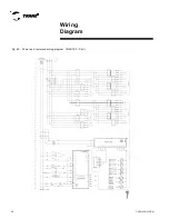
Страница 36: ...CGAD SVN02C EN 36 Wiring Diagram Fig 17 Power and command wiring diagram CGAD 020C Sheet 1 2...
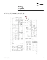
Страница 37: ...CGAD SVN02C EN 37 Wiring Diagram Fig 18 Power and command wiring diagram CGAD 020C Sheet 2 2 Part I...
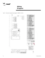
Страница 38: ...CGAD SVN02C EN 38 Fig 19 Power and command wiring diagram CGAD 020C Sheet 2 2 Part II Wiring Diagram...
Страница 40: ...CGAD SVN02C EN 40 Wiring Diagram Fig 21 Power and command wiring diagram CGAD025C CGAD030C Sheet 1 2...
Страница 41: ...CGAD SVN02C EN 41 Wiring Diagram Fig 22 Power and command wiring diagram CGAD 025C CGAD030C Sheet 2 2 Part I...
Страница 42: ...CGAD SVN02C EN 42 Wiring Diagram Fig 23 Power and command wiring diagram CGAD 025C CGAD030C Sheet 2 2 Part II...
Страница 44: ...CGAD SVN02C EN 44 Wiring Diagram Fig 25 Power and command wiring diagram CGAD040C Sheet 1 2 Part I...
Страница 45: ...CGAD SVN02C EN 45 Wiring Diagram Fig 26 Power and command wiring diagram CGAD040C Sheet 2 2 Part I...
Страница 46: ...CGAD SVN02C EN 46 Fig 27 Power and command wiring diagram CGAD040C Sheet 2 2 Part II Wiring Diagram...
Страница 48: ...CGAD SVN02C EN 48 Wiring Diagram Fig 29 Power and command wiring diagram CGAD 050C CGAD060C Sheet 1 2...
Страница 49: ...CGAD SVN02C EN 49 Wiring Diagram Fig 30 Power and command wiring diagram CGAD 050C CGAD060C Sheet 2 2 Part I...
Страница 50: ...CGAD SVN02C EN 50 Fig 31 Power and command wiring diagram CGAD 050C CGAD060C Sheet 2 2 Part II Wiring Diagram...
Страница 51: ...CGAD SVN02C EN 51 Wiring Diagram Fig 32 Layout CGAD 050C CGAD060C PATENTEADO ISOL A O V 2500 L1 L2 L3...
Страница 52: ...CGAD SVN02C EN 52 Wiring Diagram Fig 33 Power and command wiring diagram CGAD 070C Sheet 1 2...
Страница 53: ...CGAD SVN02C EN 53 Wiring Diagram Fig 34 Power and command wiring diagram CGAD 070C Sheet 2 2 Part I...
Страница 54: ...CGAD SVN02C EN 54 Wiring Diagram Fig 35 Power and command wiring diagram CGAD 070C Sheet 2 2 Part II...
Страница 56: ...CGAD SVN02C EN 56 Wiring Diagram Fig 37 Power and command wiring diagram CGAD080C CGAD090C Sheet 1 2...
Страница 57: ...CGAD SVN02C EN 57 Wiring Diagram Fig 38 Power and command wiring diagram CGAD080C CGAD090C Sheet 2 2 Part I...
Страница 58: ...CGAD SVN02C EN 58 Wiring Diagram Fig 39 Power and command wiring diagram CGAD080C CGAD090C Sheet 2 2 Part II...
Страница 60: ...CGAD SVN02C EN 60 Wiring Diagram Fig 41 Power and command wiring diagram CGAD100 Part I...
Страница 61: ...CGAD SVN02C EN 61 Wiring Diagram Fig 42 Power and command wiring diagram CGAD100 Part II...
Страница 62: ...CGAD SVN02C EN 62 Wiring Diagram Fig 43 Power and command wiring diagram CGAD100 Part III...
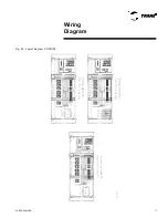
Страница 63: ...CGAD SVN02C EN 63 Wiring Diagram Fig 44 Layout diagram CGAD100...
Страница 64: ...CGAD SVN02C EN 64 Wiring Diagram Fig 45 Power and command wiring diagram CGAD120 Part I...
Страница 65: ...CGAD SVN02C EN 65 Wiring Diagram Fig 46 Power and command wiring diagram CGAD120 Part II...
Страница 66: ...CGAD SVN02C EN 66 Wiring Diagram Fig 47 Power and command wiring diagram CGAD 120 Part III...
Страница 67: ...CGAD SVN02C EN 67 Wiring Diagram Fig 48 Layout diagram CGAD 120...
Страница 68: ...CGAD SVN02C EN 68 Wiring Diagram Fig 49 Power and command wiring diagram CGAD150 Part I...
Страница 69: ...CGAD SVN02C EN 69 Wiring Diagram Fig 50 Power and command wiring diagram CGAD150 Part II...
Страница 70: ...CGAD SVN02C EN 70 Wiring Diagram Fig 51 Power and command wiring diagram CGAD150 Part III...
Страница 71: ...CGAD SVN02C EN 71 Fig 52 Layout diagram CGAD150 Wiring Diagram...
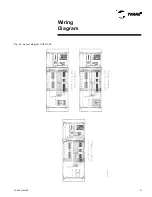
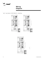
Страница 72: ...CGAD SVN02C EN 72 Wiring Diagram Fig 53 Layout diagram CGAD 100 125 150 with optionals...

