CGAD-SVN02C-EN
10
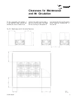
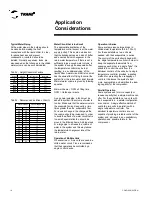
Clearance between Units and
Sound Pressure (dBA)
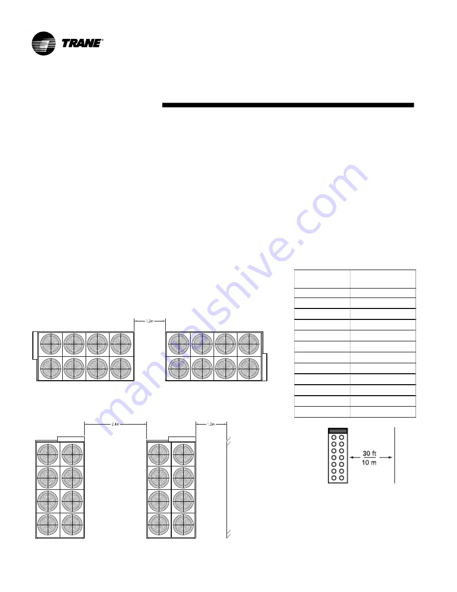
Make sure that there is enough space
around the unit externally in order to allow
the installation and maintenance team to
have unrestricted access to all service
points. Check the unit's dimensions in the
drawings that were approved. We
recommend a minimum of 4 feet (1.2 m)
for servicing the compressor. Make sure
there is enough space to open the control
panel doors. Above all, any local codes that
determine additional spaces needed have
priority over these recommendations.
The warm air recirculation and the
depletion of the coil cause a reduction in
the unit's efficiency and capacity due to an
increase in the charge pressures. Do not
allow residues, trash, and other materials
to accumulate around the unit. The
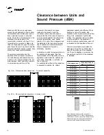
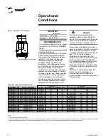
Fig. 05b - Recommended clearances - between units
Fig. 05a - Recommended clearances - horizontal assembly
CGA D020C
64
CGA D025C
65
CGA D030C
65
CGA D040C
67
CGA D050C
68
CGA D060C
68
CGA D070C
70
CGA D080C
72
CGA D090C
72
CGA D100C
72
CGA D120C
74
CGA D150C
74
Pr e s s ão Sonor a
(dbA) a 10 m e tr os
Equipam e nto
Notes: Measurements are made on the side of
equipment at distance of 10 meters. Measurements
smaller than 10 meters may provide diferents results
because the large size of equipment and different
sources of noise located in defferent positions.
movement of air supply can cause
residues to be sucked up into the
condenser coil and block the spaces
between the fins of the coil and cause the
coil to become depleted. The units for low
ambient temperatures need special
attention. The coils of the condensers and
the discharge of the fans should be kept
free of snow and of other obstructions to
allow an adequate air flow and a
satisfactory operation.
In situations in which the equipment has to
be installed with less space than that
recommended, which frequently occurs in
applications with retroactive updates and
with ceiling assemblies, a restricted air
flow is common.
An unobstructed air flow for the condenser
is essential to maintain the chiller's
operational capacity and efficiency. When
deciding on the unit's position, plan
carefully in order to ensure enough air flow
through the condenser's heat transfer
surface. Two possible harmful conditions
must be avoided for the equipment to
reach its optimum performance: warm air
recirculation and the depletion of the coil.
Warm air recirculation occurs when the
discharge air from the condenser fans is
blown to the entrance of the condenser
coil. The coil's depletion occurs when the
free air-flow (or part of it) to the condenser
is restricted.
Содержание CGAD020
Страница 36: ...CGAD SVN02C EN 36 Wiring Diagram Fig 17 Power and command wiring diagram CGAD 020C Sheet 1 2...
Страница 37: ...CGAD SVN02C EN 37 Wiring Diagram Fig 18 Power and command wiring diagram CGAD 020C Sheet 2 2 Part I...
Страница 38: ...CGAD SVN02C EN 38 Fig 19 Power and command wiring diagram CGAD 020C Sheet 2 2 Part II Wiring Diagram...
Страница 40: ...CGAD SVN02C EN 40 Wiring Diagram Fig 21 Power and command wiring diagram CGAD025C CGAD030C Sheet 1 2...
Страница 41: ...CGAD SVN02C EN 41 Wiring Diagram Fig 22 Power and command wiring diagram CGAD 025C CGAD030C Sheet 2 2 Part I...
Страница 42: ...CGAD SVN02C EN 42 Wiring Diagram Fig 23 Power and command wiring diagram CGAD 025C CGAD030C Sheet 2 2 Part II...
Страница 44: ...CGAD SVN02C EN 44 Wiring Diagram Fig 25 Power and command wiring diagram CGAD040C Sheet 1 2 Part I...
Страница 45: ...CGAD SVN02C EN 45 Wiring Diagram Fig 26 Power and command wiring diagram CGAD040C Sheet 2 2 Part I...
Страница 46: ...CGAD SVN02C EN 46 Fig 27 Power and command wiring diagram CGAD040C Sheet 2 2 Part II Wiring Diagram...
Страница 48: ...CGAD SVN02C EN 48 Wiring Diagram Fig 29 Power and command wiring diagram CGAD 050C CGAD060C Sheet 1 2...
Страница 49: ...CGAD SVN02C EN 49 Wiring Diagram Fig 30 Power and command wiring diagram CGAD 050C CGAD060C Sheet 2 2 Part I...
Страница 50: ...CGAD SVN02C EN 50 Fig 31 Power and command wiring diagram CGAD 050C CGAD060C Sheet 2 2 Part II Wiring Diagram...
Страница 51: ...CGAD SVN02C EN 51 Wiring Diagram Fig 32 Layout CGAD 050C CGAD060C PATENTEADO ISOL A O V 2500 L1 L2 L3...
Страница 52: ...CGAD SVN02C EN 52 Wiring Diagram Fig 33 Power and command wiring diagram CGAD 070C Sheet 1 2...
Страница 53: ...CGAD SVN02C EN 53 Wiring Diagram Fig 34 Power and command wiring diagram CGAD 070C Sheet 2 2 Part I...
Страница 54: ...CGAD SVN02C EN 54 Wiring Diagram Fig 35 Power and command wiring diagram CGAD 070C Sheet 2 2 Part II...
Страница 56: ...CGAD SVN02C EN 56 Wiring Diagram Fig 37 Power and command wiring diagram CGAD080C CGAD090C Sheet 1 2...
Страница 57: ...CGAD SVN02C EN 57 Wiring Diagram Fig 38 Power and command wiring diagram CGAD080C CGAD090C Sheet 2 2 Part I...
Страница 58: ...CGAD SVN02C EN 58 Wiring Diagram Fig 39 Power and command wiring diagram CGAD080C CGAD090C Sheet 2 2 Part II...
Страница 60: ...CGAD SVN02C EN 60 Wiring Diagram Fig 41 Power and command wiring diagram CGAD100 Part I...
Страница 61: ...CGAD SVN02C EN 61 Wiring Diagram Fig 42 Power and command wiring diagram CGAD100 Part II...
Страница 62: ...CGAD SVN02C EN 62 Wiring Diagram Fig 43 Power and command wiring diagram CGAD100 Part III...
Страница 63: ...CGAD SVN02C EN 63 Wiring Diagram Fig 44 Layout diagram CGAD100...
Страница 64: ...CGAD SVN02C EN 64 Wiring Diagram Fig 45 Power and command wiring diagram CGAD120 Part I...
Страница 65: ...CGAD SVN02C EN 65 Wiring Diagram Fig 46 Power and command wiring diagram CGAD120 Part II...
Страница 66: ...CGAD SVN02C EN 66 Wiring Diagram Fig 47 Power and command wiring diagram CGAD 120 Part III...
Страница 67: ...CGAD SVN02C EN 67 Wiring Diagram Fig 48 Layout diagram CGAD 120...
Страница 68: ...CGAD SVN02C EN 68 Wiring Diagram Fig 49 Power and command wiring diagram CGAD150 Part I...
Страница 69: ...CGAD SVN02C EN 69 Wiring Diagram Fig 50 Power and command wiring diagram CGAD150 Part II...
Страница 70: ...CGAD SVN02C EN 70 Wiring Diagram Fig 51 Power and command wiring diagram CGAD150 Part III...
Страница 71: ...CGAD SVN02C EN 71 Fig 52 Layout diagram CGAD150 Wiring Diagram...
Страница 72: ...CGAD SVN02C EN 72 Wiring Diagram Fig 53 Layout diagram CGAD 100 125 150 with optionals...


