CGAD-SVN02C-EN
30
Electrical Phasing of the Scroll
Compressor
It is very important that the right rotation of
the Scroll Compressor is established
before the equipment starts up. The
correct rotation of the motor needs the
confirmation of the sequence of phases
from the supply electrical energy. The
motor is internally connected to turn
clockwise with the phased energy supply
in A, B, and C. In order to confirm the
energy's correct sequence (ABC), use the
phasemeter model 45 or similar one.
Basically the voltage generated at each
phase by a polyphase alternator is called
the phase voltage. In a three-phase circuit,
three voltage solenoids are generated,
dephased by 120 electric degrees. The
order in which the three voltages of the
three-phase system succeed each other
is called the phase sequence or rotation
phase. This is determined by the direction
of the rotation of an alternator. When the
rotation is clockwise, the phase sequence
is called "ABC"; when the direction is
counterclockwise, it is "CBA".
This direction can be changed outside the
alternator by swapping any one of the
cables of the energy supply line. This
possible need of interchanging cables
makes it so that the operator needs to use
the phasemeter in order to quickly
determine the motor's rotation.
Correcting an Improper Phase Sequence
The correct phase sequence of the electric
motor can be quickly determined and
corrected before the unit starts up. Use an
instrument with a quality similar to the
Model 45 phasemeter and carry out the
following procedure:
2.1. Put the unit's RCM switch in the OFF
position.
2.2. Open the circuit's protective
disconnect that supplies energy to the
power terminals.
2.3.Turn on the phasemeter at the outlet of
the disconnect.
2.4.Turn on the electric energy by closing
the disconnect.
2.5 Read the phase sequence shown on
the indicator. The ABC led indicates that the
phase sequence is ABC.
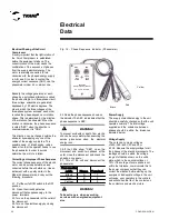
P has emeter
c able
P has e
Terminal
Black
A
1
Red
B
2
Yellow
C
3
Electrical
Data
Fig. 12 - Phase Sequence Indicator (Phasemeter)
AB C
C B A
Black
Red
Yellow
Yellow
Red
Black
Model 45
Phase sequence indicator
90
700V
60 C.P.S.
Amarelo
Vermelho
Preto
Yel low
Red
Black
WARNING!
!
Take extra care when executing
services with energized equipment
sinc
To prevent accidents or death from electric
shocks, be very careful when executing the
service procedures when the electrical
energy is on.
WARNING!
!
2.6.If the LEDs show "CBA", open the
disconnect and switch two phases at the
outlet, close the disconnect, and check the
phasing once again.
2.7. Turn off the unit and disconnect the
phasemeter.
Power Supply
The supply of electrical energy to the unit
should be carefully checked so that the unit
operates normally. The total voltage
supplied and the unbalance between
phases should be within the tolerances
indicated below:
Voltage Supply
The units can come as voltages
of 220 / 380 / 440V, 3P, and 50 or
60 Hz. Measure the supply voltage for all
the phases of the electric disconnects. The
readings should be within the voltage
range of utilization shown on the unit's
plate, which is the nominal v/-
10%. If the voltage of some phase is not
within the tolerance, communicate this to
the power company so that they can
correct the situation before starting up the
equipment. Inadequate voltage in the unit
will cause poor operation in the controls
and will shorten the life of the contacts on
the contactors and electric motors.
Содержание CGAD020
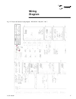
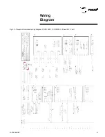
Страница 36: ...CGAD SVN02C EN 36 Wiring Diagram Fig 17 Power and command wiring diagram CGAD 020C Sheet 1 2...
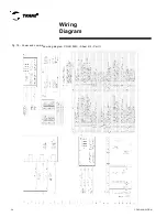
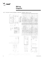
Страница 37: ...CGAD SVN02C EN 37 Wiring Diagram Fig 18 Power and command wiring diagram CGAD 020C Sheet 2 2 Part I...
Страница 38: ...CGAD SVN02C EN 38 Fig 19 Power and command wiring diagram CGAD 020C Sheet 2 2 Part II Wiring Diagram...
Страница 40: ...CGAD SVN02C EN 40 Wiring Diagram Fig 21 Power and command wiring diagram CGAD025C CGAD030C Sheet 1 2...
Страница 41: ...CGAD SVN02C EN 41 Wiring Diagram Fig 22 Power and command wiring diagram CGAD 025C CGAD030C Sheet 2 2 Part I...
Страница 42: ...CGAD SVN02C EN 42 Wiring Diagram Fig 23 Power and command wiring diagram CGAD 025C CGAD030C Sheet 2 2 Part II...
Страница 44: ...CGAD SVN02C EN 44 Wiring Diagram Fig 25 Power and command wiring diagram CGAD040C Sheet 1 2 Part I...
Страница 45: ...CGAD SVN02C EN 45 Wiring Diagram Fig 26 Power and command wiring diagram CGAD040C Sheet 2 2 Part I...
Страница 46: ...CGAD SVN02C EN 46 Fig 27 Power and command wiring diagram CGAD040C Sheet 2 2 Part II Wiring Diagram...
Страница 48: ...CGAD SVN02C EN 48 Wiring Diagram Fig 29 Power and command wiring diagram CGAD 050C CGAD060C Sheet 1 2...
Страница 49: ...CGAD SVN02C EN 49 Wiring Diagram Fig 30 Power and command wiring diagram CGAD 050C CGAD060C Sheet 2 2 Part I...
Страница 50: ...CGAD SVN02C EN 50 Fig 31 Power and command wiring diagram CGAD 050C CGAD060C Sheet 2 2 Part II Wiring Diagram...
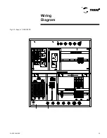
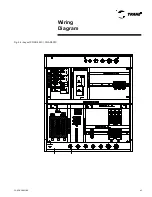
Страница 51: ...CGAD SVN02C EN 51 Wiring Diagram Fig 32 Layout CGAD 050C CGAD060C PATENTEADO ISOL A O V 2500 L1 L2 L3...
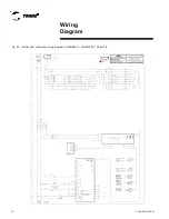
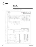
Страница 52: ...CGAD SVN02C EN 52 Wiring Diagram Fig 33 Power and command wiring diagram CGAD 070C Sheet 1 2...
Страница 53: ...CGAD SVN02C EN 53 Wiring Diagram Fig 34 Power and command wiring diagram CGAD 070C Sheet 2 2 Part I...
Страница 54: ...CGAD SVN02C EN 54 Wiring Diagram Fig 35 Power and command wiring diagram CGAD 070C Sheet 2 2 Part II...
Страница 56: ...CGAD SVN02C EN 56 Wiring Diagram Fig 37 Power and command wiring diagram CGAD080C CGAD090C Sheet 1 2...
Страница 57: ...CGAD SVN02C EN 57 Wiring Diagram Fig 38 Power and command wiring diagram CGAD080C CGAD090C Sheet 2 2 Part I...
Страница 58: ...CGAD SVN02C EN 58 Wiring Diagram Fig 39 Power and command wiring diagram CGAD080C CGAD090C Sheet 2 2 Part II...
Страница 60: ...CGAD SVN02C EN 60 Wiring Diagram Fig 41 Power and command wiring diagram CGAD100 Part I...
Страница 61: ...CGAD SVN02C EN 61 Wiring Diagram Fig 42 Power and command wiring diagram CGAD100 Part II...
Страница 62: ...CGAD SVN02C EN 62 Wiring Diagram Fig 43 Power and command wiring diagram CGAD100 Part III...
Страница 63: ...CGAD SVN02C EN 63 Wiring Diagram Fig 44 Layout diagram CGAD100...
Страница 64: ...CGAD SVN02C EN 64 Wiring Diagram Fig 45 Power and command wiring diagram CGAD120 Part I...
Страница 65: ...CGAD SVN02C EN 65 Wiring Diagram Fig 46 Power and command wiring diagram CGAD120 Part II...
Страница 66: ...CGAD SVN02C EN 66 Wiring Diagram Fig 47 Power and command wiring diagram CGAD 120 Part III...
Страница 67: ...CGAD SVN02C EN 67 Wiring Diagram Fig 48 Layout diagram CGAD 120...
Страница 68: ...CGAD SVN02C EN 68 Wiring Diagram Fig 49 Power and command wiring diagram CGAD150 Part I...
Страница 69: ...CGAD SVN02C EN 69 Wiring Diagram Fig 50 Power and command wiring diagram CGAD150 Part II...
Страница 70: ...CGAD SVN02C EN 70 Wiring Diagram Fig 51 Power and command wiring diagram CGAD150 Part III...
Страница 71: ...CGAD SVN02C EN 71 Fig 52 Layout diagram CGAD150 Wiring Diagram...
Страница 72: ...CGAD SVN02C EN 72 Wiring Diagram Fig 53 Layout diagram CGAD 100 125 150 with optionals...

