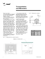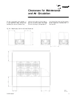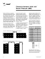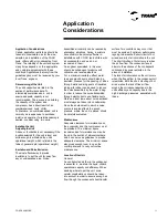
CGAD-SVN02C-EN
18
Operational
Conditions
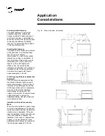
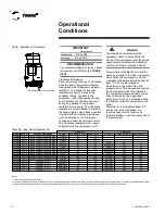
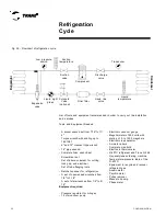
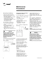
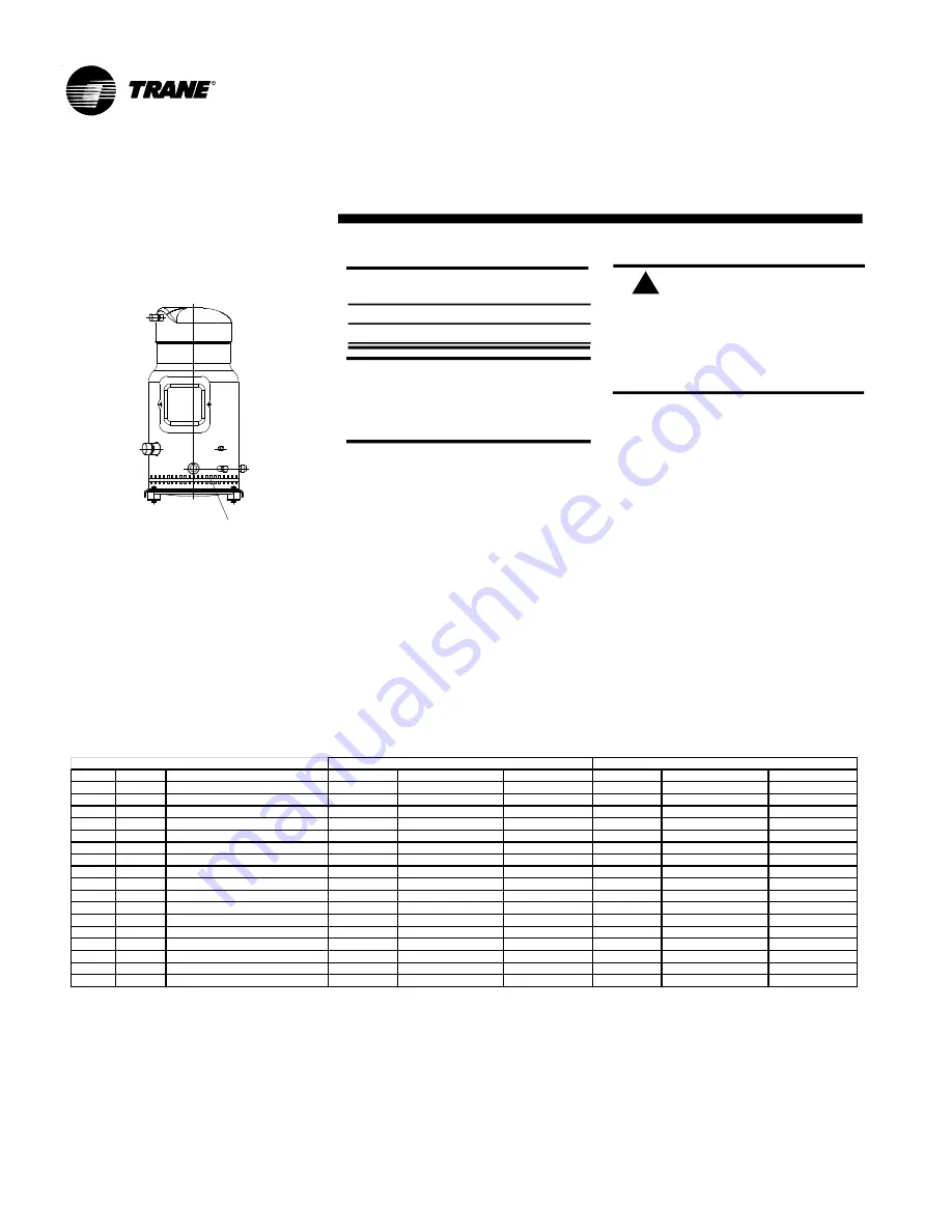
Fig.08 - Resistance of crankcase
Recommended for position fixing
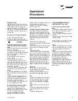
Crankcase Resistance
Trane recommends the use of crankcase
when the load of the system refrigerant
load exceeds the refrigerant compressor
limit (RCL). The needs of crankcase
resistance are directly related to the
possibility of liquid migration to the
compressor, and consequently causing
poor lubrication of it. Migration can occur
during long periods of compressor
shutdown (over 8 hours). The crankcase
resistance is recommended to eliminate
the liquid migration when these downtime
long periods.The crankcase resistance
must be installed on the compressor
housing and below the removal oil point.
The crankcase resistance must remain
energized while the compressor is off.
Attention:
The strength of crankcase must be
energized at least 12 hours before the
startup of the compressor (with the service
valves open) and should be maintained
until the compressor energized startup.
!
This will prevent the dilution of oil and the
bearings overload in the initial compressor
starts. When the compressor is off, the
crankcase temperature should be kept at
least 10°C above the refrigerant
temperature in the suction side (low
pressure side). This requirement ensures
that the refrigerant will not be retained in
the compressor crankcase. Tests can be
done to ensure that the appropriate
temperature of the oil is maintained below
the ambient conditions (temperature and
wind).
Therefore, for a temperature below -5°C
and an over 5m/s wind speed, it is
recommended that the resistors be
thermally isolated to limit the energy loss to
the environment.
Notes:
1)oilload, refers tothe total filed replacement.
2)In retrofit ormaintenanceprocedures, the idealisthat there is no mineral oilandsynthetic oilmixture! Themaximum percentage ofmixture of mineral andsyntheticoil is5%.Forexample, fora retrofitoperation ofR407C,
when the chillerwill beloaded with 20 liters of syntheticoilwill be tolerateinthesystem up to 1 literof mineraloil. Itapplies the same ruleintheconversion ofsyntheticoilformineral oil.
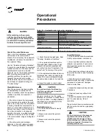
IMPORTANT
Temperatures
Superheating
5° C to 10°C
Subcooling
6° C to 12° C
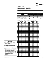
Table 04 - load and Refrigerant Oil
RECOMMENDATION
The oil recommended by Trane do Brasil
to be used on the CGAD units is
TRANE
OIL 48
.
M ODEL REFRIG.
OLEO RECOM M ENDED
COM P R.1
CARGO REFRIG.(Kg) CARGO OLEO (L)
COM P R.2
CARGO REFRIG.(Kg) CARGO OLEO (L)
CGAD020
R407C
TRANE OIL-00048 ouDANFOSS 160SZ
2xSZ125
18,5
7,6
CGAD025
R407C
TRANE OIL-00048 ouDANFOSS 160SZ
SZ125/SZ185
22,0
10,0
CGAD030
R407C
TRANE OIL-00048 ouDANFOSS 160SZ
2xSZ185
24,0
12,4
CGAD040
R407C
TRANE OIL-00048 ouDANFOSS 160SZ
2xSZ125
18,0
7,6
2xSZ125
18,0
7,6
CGAD050
R407C
TRANE OIL-00048 ouDANFOSS 160SZ
SZ125/SZ185
22,5
10,0
SZ125/SZ185
22,5
10,0
CGAD060
R407C
TRANE OIL-00048 ouDANFOSS 160SZ
2xSZ185
27,0
12,4
2xSZ185
27,0
12,4
CGAD070
R407C
TRANE OIL-00048 ouDANFOSS 160SZ
SZ185
31,5
13,8
SZ185
31,5
13,8
CGAD080
R407C
TRANE OIL-00048 ouDANFOSS 160SZ
SZ125
36,0
16,2
SZ125
36,0
16,2
CGAD090
R407C
TRANE OIL-00048 ouDANFOSS 160SZ
3xSZ185
40,5
18,6
3xSZ185
40,5
18,6
CGAD100
R407C
TRANE OIL-00048 ou DANFOSS 320 SZ
2x SY300
41,0
17,5
2 xSY300
41,0
17,5
CGAD120
R407C
TRANE OIL-00048 ou DANFOSS 320 SZ
3x SY240
66,0
26,0
3 xSY240
66,0
26,0
CGAD150
R407C
TRANE OIL-00048 ou DANFOSS 320 SZ
3x SY300
66,0
26,0
3 xSY300
66,0
26,0
CGAD100
R407C
COPELAND 3MAF (*)
2XZR300KCE
41,0
11,2
2XZR300KCE
41,0
11,2
CGAD100
R407C
COPELAND 3MAF (*)
2XZR310KCE
41,0
11,2
2XZR310KCE
41,0
11,2
CGAD120
R407C
COPELAND 3MAF (*)
3XZR250KCE
66,0
13,2
3XZR250KCE
66,0
13,2
CGAD150
R407C
COPELAND 3MAF (*)
3XZR300KCE
66,0
16,8
3XZR300KCE
66,0
16,8
CGAD150
R407C
COPELAND 3MAF (*)
3XZR310KCE
66,0
16,8
3XZR310KCE
66,0
16,8
CIRCUIT 01
CIRCUIT 02
Содержание CGAD020
Страница 36: ...CGAD SVN02C EN 36 Wiring Diagram Fig 17 Power and command wiring diagram CGAD 020C Sheet 1 2...
Страница 37: ...CGAD SVN02C EN 37 Wiring Diagram Fig 18 Power and command wiring diagram CGAD 020C Sheet 2 2 Part I...
Страница 38: ...CGAD SVN02C EN 38 Fig 19 Power and command wiring diagram CGAD 020C Sheet 2 2 Part II Wiring Diagram...
Страница 40: ...CGAD SVN02C EN 40 Wiring Diagram Fig 21 Power and command wiring diagram CGAD025C CGAD030C Sheet 1 2...
Страница 41: ...CGAD SVN02C EN 41 Wiring Diagram Fig 22 Power and command wiring diagram CGAD 025C CGAD030C Sheet 2 2 Part I...
Страница 42: ...CGAD SVN02C EN 42 Wiring Diagram Fig 23 Power and command wiring diagram CGAD 025C CGAD030C Sheet 2 2 Part II...
Страница 44: ...CGAD SVN02C EN 44 Wiring Diagram Fig 25 Power and command wiring diagram CGAD040C Sheet 1 2 Part I...
Страница 45: ...CGAD SVN02C EN 45 Wiring Diagram Fig 26 Power and command wiring diagram CGAD040C Sheet 2 2 Part I...
Страница 46: ...CGAD SVN02C EN 46 Fig 27 Power and command wiring diagram CGAD040C Sheet 2 2 Part II Wiring Diagram...
Страница 48: ...CGAD SVN02C EN 48 Wiring Diagram Fig 29 Power and command wiring diagram CGAD 050C CGAD060C Sheet 1 2...
Страница 49: ...CGAD SVN02C EN 49 Wiring Diagram Fig 30 Power and command wiring diagram CGAD 050C CGAD060C Sheet 2 2 Part I...
Страница 50: ...CGAD SVN02C EN 50 Fig 31 Power and command wiring diagram CGAD 050C CGAD060C Sheet 2 2 Part II Wiring Diagram...
Страница 51: ...CGAD SVN02C EN 51 Wiring Diagram Fig 32 Layout CGAD 050C CGAD060C PATENTEADO ISOL A O V 2500 L1 L2 L3...
Страница 52: ...CGAD SVN02C EN 52 Wiring Diagram Fig 33 Power and command wiring diagram CGAD 070C Sheet 1 2...
Страница 53: ...CGAD SVN02C EN 53 Wiring Diagram Fig 34 Power and command wiring diagram CGAD 070C Sheet 2 2 Part I...
Страница 54: ...CGAD SVN02C EN 54 Wiring Diagram Fig 35 Power and command wiring diagram CGAD 070C Sheet 2 2 Part II...
Страница 56: ...CGAD SVN02C EN 56 Wiring Diagram Fig 37 Power and command wiring diagram CGAD080C CGAD090C Sheet 1 2...
Страница 57: ...CGAD SVN02C EN 57 Wiring Diagram Fig 38 Power and command wiring diagram CGAD080C CGAD090C Sheet 2 2 Part I...
Страница 58: ...CGAD SVN02C EN 58 Wiring Diagram Fig 39 Power and command wiring diagram CGAD080C CGAD090C Sheet 2 2 Part II...
Страница 60: ...CGAD SVN02C EN 60 Wiring Diagram Fig 41 Power and command wiring diagram CGAD100 Part I...
Страница 61: ...CGAD SVN02C EN 61 Wiring Diagram Fig 42 Power and command wiring diagram CGAD100 Part II...
Страница 62: ...CGAD SVN02C EN 62 Wiring Diagram Fig 43 Power and command wiring diagram CGAD100 Part III...
Страница 63: ...CGAD SVN02C EN 63 Wiring Diagram Fig 44 Layout diagram CGAD100...
Страница 64: ...CGAD SVN02C EN 64 Wiring Diagram Fig 45 Power and command wiring diagram CGAD120 Part I...
Страница 65: ...CGAD SVN02C EN 65 Wiring Diagram Fig 46 Power and command wiring diagram CGAD120 Part II...
Страница 66: ...CGAD SVN02C EN 66 Wiring Diagram Fig 47 Power and command wiring diagram CGAD 120 Part III...
Страница 67: ...CGAD SVN02C EN 67 Wiring Diagram Fig 48 Layout diagram CGAD 120...
Страница 68: ...CGAD SVN02C EN 68 Wiring Diagram Fig 49 Power and command wiring diagram CGAD150 Part I...
Страница 69: ...CGAD SVN02C EN 69 Wiring Diagram Fig 50 Power and command wiring diagram CGAD150 Part II...
Страница 70: ...CGAD SVN02C EN 70 Wiring Diagram Fig 51 Power and command wiring diagram CGAD150 Part III...
Страница 71: ...CGAD SVN02C EN 71 Fig 52 Layout diagram CGAD150 Wiring Diagram...
Страница 72: ...CGAD SVN02C EN 72 Wiring Diagram Fig 53 Layout diagram CGAD 100 125 150 with optionals...

