CGAD-SVN02C-EN
16
Checklist for Initial Start
General
Once the units are installed, complete
each item of this list. When they are all
complete, the units will be ready for starting
up.
[ ] Make sure that the installation voltage is
the same as the CGAD liquid chiller and
other components.
[ ] Inspect all the electric connections. They
should be clean and tight.
[ ] Check the oil level in the crankcase of
the compressors. The oil should be visible
in the oil-level sight glass.
[ ] Check the sequence of the phases as
described in the power supply drawings.
[ ] Check the correct installation of all the
temperature sensors.
[ ] Close the unit's power disconnect
switch and the command circuit breakers.
The switch for the CGAD liquid chiller unit
should be in the OFF position.
[ ] Complete the chilled water circuit
(evaporator). Read also the "Water
System" of the evaporator in this manual.
[ ] Close the circuit breakers or
disconnecting switches with fuses that
provide energy to the starting switches of
the chilled water pump.
[ ] Turn on the chilled water pump. With the
water circulating, check all the tubing
connections in order to detect possible
leaks. Make any repairs that may be
needed.
[ ] With the water pump on, adjust the
water flow, and check the loss of pressure
through the evaporator. Write down the
Checklist
for Initial Start
WARNING!
!
In order to prevent accidents or deaths
from electric shocks, open and lock in
place all the circuit breakers and electric
disconnects.
WARNING!
!
In order to avoid damaging the
compressors, do not operate the unit
with any of the access valves of suction,
discharge, or liquid while they are closed.
levels obtained.
[ ] Adjust the water flow switch on the
chilled water tubing and make sure that it
is working correctly.
[ ] Turn off the pumps. The unit is ready to
start up. Follow the instructions of
operation, maintenance, and
complementary procedures for starting up
the unit.
Check the procedures in this manual to
complete the gas charge.
CAUTION:
!
In order to avoid superheat, the
connections and low voltage conditions
in the compressor motor, make sure that
all the connections are tight on the
compressor's electrical circuit.
[ ] Loosen the bolts of the rubber pads on
each compressor if this has not been
done yet.
[ ] Open the valves of the lines of suction,
liquid, and the service valve of discharge.
[ ] Make sure that there are no refrigerant
leaks.
[ ] Check the voltage (energy supply) for the
unit at the disconnect switch and power
fuses. The voltage should be within the
ranges stated on tables 10 and 11 (as well
as printed on the equipment's identification
plates). The voltage unbalance should not
exceed 2% - check page 30 of this
manual.
CAUTION:
!
In order to avoid damaging the
equipment, don't use untreated or poorly
treated water in the system. The use of
inappropriate water will result in the
equipment losing its warranty.
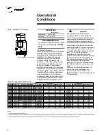
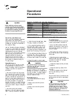
Rated Voltage
Operation Range(V)
220V/60Hz
180-253
380V/60Hz
342-418
440V/60Hz
414-506
380V/50 Hz
340-440
Содержание CGAD020
Страница 36: ...CGAD SVN02C EN 36 Wiring Diagram Fig 17 Power and command wiring diagram CGAD 020C Sheet 1 2...
Страница 37: ...CGAD SVN02C EN 37 Wiring Diagram Fig 18 Power and command wiring diagram CGAD 020C Sheet 2 2 Part I...
Страница 38: ...CGAD SVN02C EN 38 Fig 19 Power and command wiring diagram CGAD 020C Sheet 2 2 Part II Wiring Diagram...
Страница 40: ...CGAD SVN02C EN 40 Wiring Diagram Fig 21 Power and command wiring diagram CGAD025C CGAD030C Sheet 1 2...
Страница 41: ...CGAD SVN02C EN 41 Wiring Diagram Fig 22 Power and command wiring diagram CGAD 025C CGAD030C Sheet 2 2 Part I...
Страница 42: ...CGAD SVN02C EN 42 Wiring Diagram Fig 23 Power and command wiring diagram CGAD 025C CGAD030C Sheet 2 2 Part II...
Страница 44: ...CGAD SVN02C EN 44 Wiring Diagram Fig 25 Power and command wiring diagram CGAD040C Sheet 1 2 Part I...
Страница 45: ...CGAD SVN02C EN 45 Wiring Diagram Fig 26 Power and command wiring diagram CGAD040C Sheet 2 2 Part I...
Страница 46: ...CGAD SVN02C EN 46 Fig 27 Power and command wiring diagram CGAD040C Sheet 2 2 Part II Wiring Diagram...
Страница 48: ...CGAD SVN02C EN 48 Wiring Diagram Fig 29 Power and command wiring diagram CGAD 050C CGAD060C Sheet 1 2...
Страница 49: ...CGAD SVN02C EN 49 Wiring Diagram Fig 30 Power and command wiring diagram CGAD 050C CGAD060C Sheet 2 2 Part I...
Страница 50: ...CGAD SVN02C EN 50 Fig 31 Power and command wiring diagram CGAD 050C CGAD060C Sheet 2 2 Part II Wiring Diagram...
Страница 51: ...CGAD SVN02C EN 51 Wiring Diagram Fig 32 Layout CGAD 050C CGAD060C PATENTEADO ISOL A O V 2500 L1 L2 L3...
Страница 52: ...CGAD SVN02C EN 52 Wiring Diagram Fig 33 Power and command wiring diagram CGAD 070C Sheet 1 2...
Страница 53: ...CGAD SVN02C EN 53 Wiring Diagram Fig 34 Power and command wiring diagram CGAD 070C Sheet 2 2 Part I...
Страница 54: ...CGAD SVN02C EN 54 Wiring Diagram Fig 35 Power and command wiring diagram CGAD 070C Sheet 2 2 Part II...
Страница 56: ...CGAD SVN02C EN 56 Wiring Diagram Fig 37 Power and command wiring diagram CGAD080C CGAD090C Sheet 1 2...
Страница 57: ...CGAD SVN02C EN 57 Wiring Diagram Fig 38 Power and command wiring diagram CGAD080C CGAD090C Sheet 2 2 Part I...
Страница 58: ...CGAD SVN02C EN 58 Wiring Diagram Fig 39 Power and command wiring diagram CGAD080C CGAD090C Sheet 2 2 Part II...
Страница 60: ...CGAD SVN02C EN 60 Wiring Diagram Fig 41 Power and command wiring diagram CGAD100 Part I...
Страница 61: ...CGAD SVN02C EN 61 Wiring Diagram Fig 42 Power and command wiring diagram CGAD100 Part II...
Страница 62: ...CGAD SVN02C EN 62 Wiring Diagram Fig 43 Power and command wiring diagram CGAD100 Part III...
Страница 63: ...CGAD SVN02C EN 63 Wiring Diagram Fig 44 Layout diagram CGAD100...
Страница 64: ...CGAD SVN02C EN 64 Wiring Diagram Fig 45 Power and command wiring diagram CGAD120 Part I...
Страница 65: ...CGAD SVN02C EN 65 Wiring Diagram Fig 46 Power and command wiring diagram CGAD120 Part II...
Страница 66: ...CGAD SVN02C EN 66 Wiring Diagram Fig 47 Power and command wiring diagram CGAD 120 Part III...
Страница 67: ...CGAD SVN02C EN 67 Wiring Diagram Fig 48 Layout diagram CGAD 120...
Страница 68: ...CGAD SVN02C EN 68 Wiring Diagram Fig 49 Power and command wiring diagram CGAD150 Part I...
Страница 69: ...CGAD SVN02C EN 69 Wiring Diagram Fig 50 Power and command wiring diagram CGAD150 Part II...
Страница 70: ...CGAD SVN02C EN 70 Wiring Diagram Fig 51 Power and command wiring diagram CGAD150 Part III...
Страница 71: ...CGAD SVN02C EN 71 Fig 52 Layout diagram CGAD150 Wiring Diagram...
Страница 72: ...CGAD SVN02C EN 72 Wiring Diagram Fig 53 Layout diagram CGAD 100 125 150 with optionals...

