CGAD-SVN02C-EN
23
Operational
Procedures
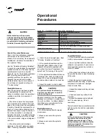
Refrigerant Charge
If the charge is done by suction, use only
refrigerant in the form of gas. Do not put the
cylinder upside down for charging the
system more quickly. If the charge is done
high side, then introduce the liquid directly
in the system using the charging valve on
the liquid line.
Procedures dor Chrageng the System
a. Open the system's disconnect.
b. Open the valves of the low and high
condition, check the condition of the bulb of
the expansion valve and replace if
necessary. Only replace the expansion
valve in the last case.
Insufficient Charging - Expansion Valve
An insufficient charge of the evaporator
results in low suction pressure and high
superheat. It can be caused by an incorrect
adjustment of the superheat, a choking of
the solenoid valve or dryer or bulb of the
valve if it is not working, or due to lack of
refrigerant.
Test the bulb in the following way:
- Stop the unit and allow it to reach ambient
temperature.
- Remove the remote bulb from the suction
line and put it in a recipient with chilled
water.
- Start up the system.
- Remove the bulb from the recipient and
warm it up in your hands. At the same time,
examine the suction. If there is little or no
change in the suction line temperature, the
bulb is defective. Replace the diaphragm
and the bulb of the valve (or the entire
valve). If the bulb is working, readjust the
superheat. If this does not correct the
problem, remove the seat of the valve and
inspect it. Replace the seat if necessary.
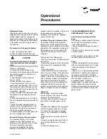
Adding Oil
Before adding oil, allow the system
to work for three or four hours. Check the
oil level at 30 minute intervals.
If the level does not return to normal (oil
level visible in the sight glass), add oil.
Test
a. Reclaim the refrigerant from the system
with the compressor itself, up to 10 psig.
b. Connect the piston-type oil charging
pump to the compressor's oil charging
valve.
c.Bleed the air from the hose with the oil
itself.
d. Open the charging valve and fill with oil
up to the level that shows on the sight
glass.
e. Close the charging valve.
THE OIL RECOMMENDED FOR THE
COMPRESSOR IS "Trane Oil 48"
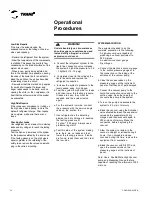
Liquid Line Solenoid Valve and Filter
Dryer
The following conditions indicate that there
is a choking of a solenoid valve or dryer.
- Low suction pressure
- Drop in temperature through the valve or
dryer filter
- Formation of ice in the valve or in the dryer
in serious cases.
If these symptoms occur, repair or replace
the valve. Change the filter dryer core.
Purge
- Reclaim the refrigerant from the system
(with the compressor itself) up to 10 psig.
- Allow the pressures in the system to
stabilize.
- Keep an eye on the discharge pressure.
If the level is 0.7 kgf/cm2 (10 psig) above
the pressure of the R-407C saturated
vapor, the ambient temperature of the air,
then the system contains non-
condensable gases. Transfer the
refrigerant gas to a cylinder, evacuate the
system, breaking the vacuum with dry
nitrogen and evacuating the system again
up to 500 microns. After this, charge the
system again.
pressure manometers.
c. Connect the R407C cylinder to the
connection of the charge valve on the liquid
line. Invert the cylinder to introduce only
liquid in the system.
d. Add refrigerant until the pressures
become stable.
e. Close the valve of the cylinder.
f. Close the disconnect and turn on the
system and begin operation. Then turn off
the compressor, which will make the unit
begin suction and stop to operate from the
low-pressure regulator.
g. Open the valve of the cylinder and allow
the entrance of liquid refrigerant into the
system.
h. Close the charging valve to the cylinder
after the estimated charge has entered the
system.
i. Leave the system operating during 30
minutes. Check the refrigerant flow in the
sight glass of the liquid line and keep an
eye on the operational pressure.
j. If bubbles appear in the sight glass, add
as much refrigerant as needed.
Excessive Charging - Expansion Valve
The excessive charging of the chiller
results in suction head pressure, low
superheat, and a possible return of liquid.
This set of conditions is generally
overcome by readjusting the valve's
superheat. If this does not correct the
The water should always be circulating
in the evaporator and in the condenser
when
CAUTION:
!
Содержание CGAD020
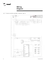
Страница 36: ...CGAD SVN02C EN 36 Wiring Diagram Fig 17 Power and command wiring diagram CGAD 020C Sheet 1 2...
Страница 37: ...CGAD SVN02C EN 37 Wiring Diagram Fig 18 Power and command wiring diagram CGAD 020C Sheet 2 2 Part I...
Страница 38: ...CGAD SVN02C EN 38 Fig 19 Power and command wiring diagram CGAD 020C Sheet 2 2 Part II Wiring Diagram...
Страница 40: ...CGAD SVN02C EN 40 Wiring Diagram Fig 21 Power and command wiring diagram CGAD025C CGAD030C Sheet 1 2...
Страница 41: ...CGAD SVN02C EN 41 Wiring Diagram Fig 22 Power and command wiring diagram CGAD 025C CGAD030C Sheet 2 2 Part I...
Страница 42: ...CGAD SVN02C EN 42 Wiring Diagram Fig 23 Power and command wiring diagram CGAD 025C CGAD030C Sheet 2 2 Part II...
Страница 44: ...CGAD SVN02C EN 44 Wiring Diagram Fig 25 Power and command wiring diagram CGAD040C Sheet 1 2 Part I...
Страница 45: ...CGAD SVN02C EN 45 Wiring Diagram Fig 26 Power and command wiring diagram CGAD040C Sheet 2 2 Part I...
Страница 46: ...CGAD SVN02C EN 46 Fig 27 Power and command wiring diagram CGAD040C Sheet 2 2 Part II Wiring Diagram...
Страница 48: ...CGAD SVN02C EN 48 Wiring Diagram Fig 29 Power and command wiring diagram CGAD 050C CGAD060C Sheet 1 2...
Страница 49: ...CGAD SVN02C EN 49 Wiring Diagram Fig 30 Power and command wiring diagram CGAD 050C CGAD060C Sheet 2 2 Part I...
Страница 50: ...CGAD SVN02C EN 50 Fig 31 Power and command wiring diagram CGAD 050C CGAD060C Sheet 2 2 Part II Wiring Diagram...
Страница 51: ...CGAD SVN02C EN 51 Wiring Diagram Fig 32 Layout CGAD 050C CGAD060C PATENTEADO ISOL A O V 2500 L1 L2 L3...
Страница 52: ...CGAD SVN02C EN 52 Wiring Diagram Fig 33 Power and command wiring diagram CGAD 070C Sheet 1 2...
Страница 53: ...CGAD SVN02C EN 53 Wiring Diagram Fig 34 Power and command wiring diagram CGAD 070C Sheet 2 2 Part I...
Страница 54: ...CGAD SVN02C EN 54 Wiring Diagram Fig 35 Power and command wiring diagram CGAD 070C Sheet 2 2 Part II...
Страница 56: ...CGAD SVN02C EN 56 Wiring Diagram Fig 37 Power and command wiring diagram CGAD080C CGAD090C Sheet 1 2...
Страница 57: ...CGAD SVN02C EN 57 Wiring Diagram Fig 38 Power and command wiring diagram CGAD080C CGAD090C Sheet 2 2 Part I...
Страница 58: ...CGAD SVN02C EN 58 Wiring Diagram Fig 39 Power and command wiring diagram CGAD080C CGAD090C Sheet 2 2 Part II...
Страница 60: ...CGAD SVN02C EN 60 Wiring Diagram Fig 41 Power and command wiring diagram CGAD100 Part I...
Страница 61: ...CGAD SVN02C EN 61 Wiring Diagram Fig 42 Power and command wiring diagram CGAD100 Part II...
Страница 62: ...CGAD SVN02C EN 62 Wiring Diagram Fig 43 Power and command wiring diagram CGAD100 Part III...
Страница 63: ...CGAD SVN02C EN 63 Wiring Diagram Fig 44 Layout diagram CGAD100...
Страница 64: ...CGAD SVN02C EN 64 Wiring Diagram Fig 45 Power and command wiring diagram CGAD120 Part I...
Страница 65: ...CGAD SVN02C EN 65 Wiring Diagram Fig 46 Power and command wiring diagram CGAD120 Part II...
Страница 66: ...CGAD SVN02C EN 66 Wiring Diagram Fig 47 Power and command wiring diagram CGAD 120 Part III...
Страница 67: ...CGAD SVN02C EN 67 Wiring Diagram Fig 48 Layout diagram CGAD 120...
Страница 68: ...CGAD SVN02C EN 68 Wiring Diagram Fig 49 Power and command wiring diagram CGAD150 Part I...
Страница 69: ...CGAD SVN02C EN 69 Wiring Diagram Fig 50 Power and command wiring diagram CGAD150 Part II...
Страница 70: ...CGAD SVN02C EN 70 Wiring Diagram Fig 51 Power and command wiring diagram CGAD150 Part III...
Страница 71: ...CGAD SVN02C EN 71 Fig 52 Layout diagram CGAD150 Wiring Diagram...
Страница 72: ...CGAD SVN02C EN 72 Wiring Diagram Fig 53 Layout diagram CGAD 100 125 150 with optionals...

