CGAD-SVN02C-EN
26
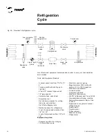
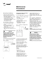
Installing a new Compressor
The compressor may present basically
two types of problems:
- Mechanical
- Electrical
In both cases the compressor should be
replaced; but remember that it is not
enough to simply put on a new
compressor. Always try to find and
eliminate what caused the defect.
a. Mechanical breakdown: If the
compressor does not have access valves
, transfer the refrigerant to an appropriate
cylinder and run the pressure test
(maximum of 200 psig to protect the low-
pressure switch), make a new vacuum,
charge refrigerant, and then start up again
with all the readings. Correct the
installation that may have damaged the
equipment, freeing it up for operation, and
always have a specialized company
monitoring it.
- If the compressor has access valves, the
refrigerant can be kept in the circuit, and
the following sequence should be
followed.
- Close the compressor's suction and
discharge valves.
- Open the nuts on the connections of the
compressor's valves and pigtails on the
pressure gauges
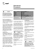
Operational
Procedures
CAUTION:
All the tests done on the pressure
regulator should be done with reliable
pressure gauges. These safety devices
are calibrated at the factory and sealed. If
violated, the warranty will be void.
!
- Turn off the compressor's electric circuit
- Remove the compressor
- Install the new or reconditioned
compressor
- Install the electric circuit and the pigtails of
the pressure gauges
- Evacuate the compressor
- Open the compressor valves
Motor burnout
Motor burnout implies in the formation of
acids and the deposit of oxides and waste
on parts of the circuit and so it is necessary
to replace the refrigerant and the oil and
clean the entire circuit by placing HH anti-
acid dryer filters in the suction and in the
liquid line. In this case, the cleaning should
be carried out in the following way:
- Reclaim all the refrigerant in a cylinder
and send it to be recycled by the
manufacturer or do your own recycling with
equipment specific for this.
- Remove the compressor.
- Remove the dryer filter.
- Install the adequate filter on the
compressor's suction line and change the
one on the liquid line.
- Install the new or reconditioned
compressor, then evacuate and charge the
system.
- Check the contactor. The contacts should
be clean or changed.
- Put the conditioner to work and monitor
its operation.
- Check the loss of pressure through the
suction filter. If the loss of pressure
exceeds that recommended by the
manufacturer, the filter should be changed.
- After 48 hours of operation, the oil should
be analyzed.
- Change the oil and filter every
48 hours until the oil is exempt of acidity.
- Remove the suction filter. When cleaning
one of the TWIN circuits (two
compressors), it is necessary to change
the oil of the compressor that burned out
and of its pair also.
NEVER RELEASE GAS INTO THE
ENVIRONMENT.
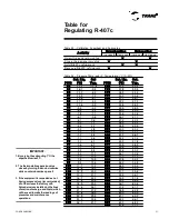
Always install a pressure regulator
at the hook-up for the testing
pressure. Set the control of the
regulator to 14 kgf /cm
2
(200 psig).
IMPORTANT
!
Содержание CGAD020
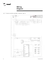
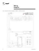
Страница 36: ...CGAD SVN02C EN 36 Wiring Diagram Fig 17 Power and command wiring diagram CGAD 020C Sheet 1 2...
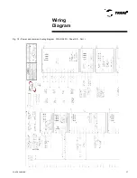
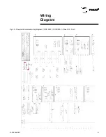
Страница 37: ...CGAD SVN02C EN 37 Wiring Diagram Fig 18 Power and command wiring diagram CGAD 020C Sheet 2 2 Part I...
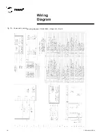
Страница 38: ...CGAD SVN02C EN 38 Fig 19 Power and command wiring diagram CGAD 020C Sheet 2 2 Part II Wiring Diagram...
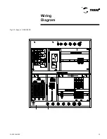
Страница 40: ...CGAD SVN02C EN 40 Wiring Diagram Fig 21 Power and command wiring diagram CGAD025C CGAD030C Sheet 1 2...
Страница 41: ...CGAD SVN02C EN 41 Wiring Diagram Fig 22 Power and command wiring diagram CGAD 025C CGAD030C Sheet 2 2 Part I...
Страница 42: ...CGAD SVN02C EN 42 Wiring Diagram Fig 23 Power and command wiring diagram CGAD 025C CGAD030C Sheet 2 2 Part II...
Страница 44: ...CGAD SVN02C EN 44 Wiring Diagram Fig 25 Power and command wiring diagram CGAD040C Sheet 1 2 Part I...
Страница 45: ...CGAD SVN02C EN 45 Wiring Diagram Fig 26 Power and command wiring diagram CGAD040C Sheet 2 2 Part I...
Страница 46: ...CGAD SVN02C EN 46 Fig 27 Power and command wiring diagram CGAD040C Sheet 2 2 Part II Wiring Diagram...
Страница 48: ...CGAD SVN02C EN 48 Wiring Diagram Fig 29 Power and command wiring diagram CGAD 050C CGAD060C Sheet 1 2...
Страница 49: ...CGAD SVN02C EN 49 Wiring Diagram Fig 30 Power and command wiring diagram CGAD 050C CGAD060C Sheet 2 2 Part I...
Страница 50: ...CGAD SVN02C EN 50 Fig 31 Power and command wiring diagram CGAD 050C CGAD060C Sheet 2 2 Part II Wiring Diagram...
Страница 51: ...CGAD SVN02C EN 51 Wiring Diagram Fig 32 Layout CGAD 050C CGAD060C PATENTEADO ISOL A O V 2500 L1 L2 L3...
Страница 52: ...CGAD SVN02C EN 52 Wiring Diagram Fig 33 Power and command wiring diagram CGAD 070C Sheet 1 2...
Страница 53: ...CGAD SVN02C EN 53 Wiring Diagram Fig 34 Power and command wiring diagram CGAD 070C Sheet 2 2 Part I...
Страница 54: ...CGAD SVN02C EN 54 Wiring Diagram Fig 35 Power and command wiring diagram CGAD 070C Sheet 2 2 Part II...
Страница 56: ...CGAD SVN02C EN 56 Wiring Diagram Fig 37 Power and command wiring diagram CGAD080C CGAD090C Sheet 1 2...
Страница 57: ...CGAD SVN02C EN 57 Wiring Diagram Fig 38 Power and command wiring diagram CGAD080C CGAD090C Sheet 2 2 Part I...
Страница 58: ...CGAD SVN02C EN 58 Wiring Diagram Fig 39 Power and command wiring diagram CGAD080C CGAD090C Sheet 2 2 Part II...
Страница 60: ...CGAD SVN02C EN 60 Wiring Diagram Fig 41 Power and command wiring diagram CGAD100 Part I...
Страница 61: ...CGAD SVN02C EN 61 Wiring Diagram Fig 42 Power and command wiring diagram CGAD100 Part II...
Страница 62: ...CGAD SVN02C EN 62 Wiring Diagram Fig 43 Power and command wiring diagram CGAD100 Part III...
Страница 63: ...CGAD SVN02C EN 63 Wiring Diagram Fig 44 Layout diagram CGAD100...
Страница 64: ...CGAD SVN02C EN 64 Wiring Diagram Fig 45 Power and command wiring diagram CGAD120 Part I...
Страница 65: ...CGAD SVN02C EN 65 Wiring Diagram Fig 46 Power and command wiring diagram CGAD120 Part II...
Страница 66: ...CGAD SVN02C EN 66 Wiring Diagram Fig 47 Power and command wiring diagram CGAD 120 Part III...
Страница 67: ...CGAD SVN02C EN 67 Wiring Diagram Fig 48 Layout diagram CGAD 120...
Страница 68: ...CGAD SVN02C EN 68 Wiring Diagram Fig 49 Power and command wiring diagram CGAD150 Part I...
Страница 69: ...CGAD SVN02C EN 69 Wiring Diagram Fig 50 Power and command wiring diagram CGAD150 Part II...
Страница 70: ...CGAD SVN02C EN 70 Wiring Diagram Fig 51 Power and command wiring diagram CGAD150 Part III...
Страница 71: ...CGAD SVN02C EN 71 Fig 52 Layout diagram CGAD150 Wiring Diagram...
Страница 72: ...CGAD SVN02C EN 72 Wiring Diagram Fig 53 Layout diagram CGAD 100 125 150 with optionals...


