CGAD-SVN02C-EN
73
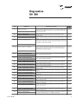
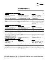
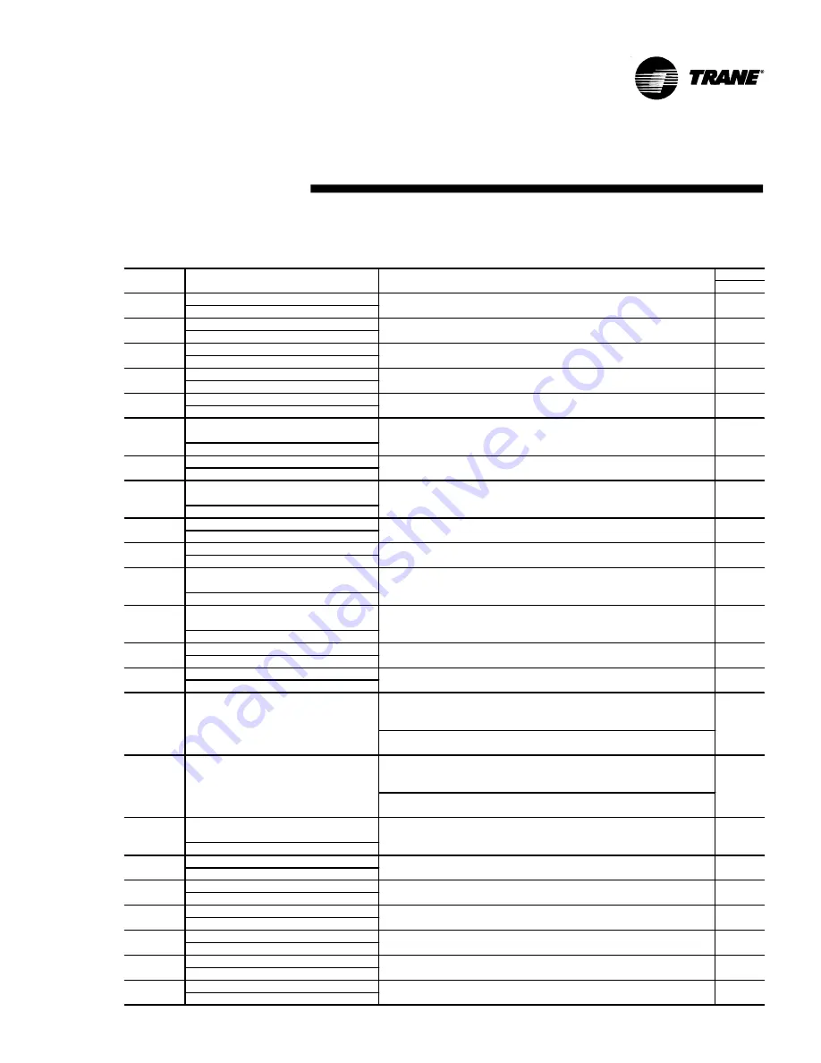
Type
Reset
Phase Reversal
Current L1Loss
Current L2 Loss
Current L3 Loss
Starter Module Memory Error Type 2
Power Loss
Starter Contactor Interrupt Failure
M P: Reset Has Occurred
Low Pressure Cutout
Low Suction Refrigerant Pressure
High M otor Temp/Overload Trip Cprsr A
High M otor Temp/Overload Trip Cprsr A
BAS Failed to Establish Communication
BAS Communication Lost
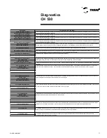
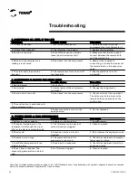
A. The external control module of the chilled water temperature setpoint received a
control voltage or current above or below the specified limits. (0 to 10 VDC or 4 to 10
ma).
B. The control module presented an operational failure or there is a bad contact on the
connection cable of the modules (LLID).
A. When activated, the operational reclaiming normally is interrupted by the low
pressure control. This message indicates that the low pressure control did not detect a
low pressure of 10PSI after 30 seconds after the beginning of the reclaiming.
When the reclaiming service is activated, the low pressure control did not detect a low
pressure of 10PSI after 1minute from the beginning of the reclaiming.
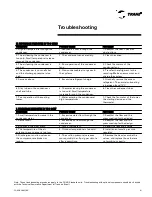
Chilled Water Flow (Entering Water Temp)
Evaporator Entering Water Temp Sensor
Evaporator Leaving Water Temp Sensor
Condenser Entering Water Temp Sensor
Condenser Leaving Water Temp Sensor
Discharge Pressure Transducer
Suction Pressure Transducer
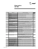
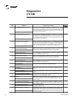
Code
Diagnost ic
Descript ion of Problem
E5
A phase reversal was detected on the equipment's energy supply.
Local
E4
The L1current sensor detected a loss of current.
Local
E4
The L2 current sensor detected a loss of current.
Local
E4
The L3 current sensor detected a loss of current.
Local
6B6
Detecting error in the configuration in the starter module memory of the compressors.
Local
1A0
The current sensors detected a three-phase power loss during the operation. If the
current is less than 10%of the nominal current, the equipment will shut down in 2.64
seconds.
Remote
CA
A current level 10%higher than the maximumcurrent of operation for the equipment was
detected on one or more phases of the three-phase power supply.
Local
D9
The controller was reset after receiving a new configuration and installation of a new
version of the control software. This message is automatically deactivated and only
visualized through the log of diagnostics.
NA
B5 or B6
The equipment's suction pressure dropped below 7 psi, causing the compressor(s) to
turn off.
Local
6B6
A suction pressure below that specified for the protection systemwas detected. This
diagnostic will be automatically reset when the pressure reaches adequate values.
Local
BA or BC
The internal thermostat of the compressor identified a high temperature or the
protection against the compressor's overload detected a current level above the
protection level established.
Local
BB or BD
The internal thermostat of the compressor identified a high temperature or the
protection against the compressor's overload detected a current level above the
protection level established.
Local
390
The controller was informed that it is linked to the Management System(BAS) and
cannot make communication with it.
Remote
398
The COM M3 communication module of the controller lost communication with the
Management System(BAS)
Remote
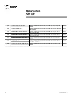
87
External Chilled Water Setpoint
Remote
8C or 8D
Circuit Pumpdown Terminated
Remote
Remote
8E
Temperature sensor has a defect or a bad contact on the connection cable of the
sensors.
Remote
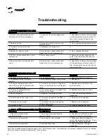
8A
It was detected that the temperature of the entering water fromthe evaporator is 3.6ºC
below the evaporator's leaving water temperature, which indicates a lack of water flow
through the evaporator.
AB
Temperature sensor has a defect or a bad contact on the connection cable of the
sensors.
Remote
9A
Temperature sensor has a defect or a bad contact on the connection cable of the
sensors.
Remote
9B
Temperature sensor has a defect or a bad contact on the connection cable of the
sensors.
Remote
6B6
Pressure transducer has a defect or a bad contact on the connection cable of the
sensors.
Remote
6B6
Pressure transducer has a defect or a bad contact on the connection cable of the
sensors.
Remote
Diagnostics
CH 530
Содержание CGAD020
Страница 36: ...CGAD SVN02C EN 36 Wiring Diagram Fig 17 Power and command wiring diagram CGAD 020C Sheet 1 2...
Страница 37: ...CGAD SVN02C EN 37 Wiring Diagram Fig 18 Power and command wiring diagram CGAD 020C Sheet 2 2 Part I...
Страница 38: ...CGAD SVN02C EN 38 Fig 19 Power and command wiring diagram CGAD 020C Sheet 2 2 Part II Wiring Diagram...
Страница 40: ...CGAD SVN02C EN 40 Wiring Diagram Fig 21 Power and command wiring diagram CGAD025C CGAD030C Sheet 1 2...
Страница 41: ...CGAD SVN02C EN 41 Wiring Diagram Fig 22 Power and command wiring diagram CGAD 025C CGAD030C Sheet 2 2 Part I...
Страница 42: ...CGAD SVN02C EN 42 Wiring Diagram Fig 23 Power and command wiring diagram CGAD 025C CGAD030C Sheet 2 2 Part II...
Страница 44: ...CGAD SVN02C EN 44 Wiring Diagram Fig 25 Power and command wiring diagram CGAD040C Sheet 1 2 Part I...
Страница 45: ...CGAD SVN02C EN 45 Wiring Diagram Fig 26 Power and command wiring diagram CGAD040C Sheet 2 2 Part I...
Страница 46: ...CGAD SVN02C EN 46 Fig 27 Power and command wiring diagram CGAD040C Sheet 2 2 Part II Wiring Diagram...
Страница 48: ...CGAD SVN02C EN 48 Wiring Diagram Fig 29 Power and command wiring diagram CGAD 050C CGAD060C Sheet 1 2...
Страница 49: ...CGAD SVN02C EN 49 Wiring Diagram Fig 30 Power and command wiring diagram CGAD 050C CGAD060C Sheet 2 2 Part I...
Страница 50: ...CGAD SVN02C EN 50 Fig 31 Power and command wiring diagram CGAD 050C CGAD060C Sheet 2 2 Part II Wiring Diagram...
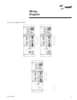
Страница 51: ...CGAD SVN02C EN 51 Wiring Diagram Fig 32 Layout CGAD 050C CGAD060C PATENTEADO ISOL A O V 2500 L1 L2 L3...
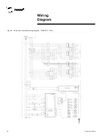
Страница 52: ...CGAD SVN02C EN 52 Wiring Diagram Fig 33 Power and command wiring diagram CGAD 070C Sheet 1 2...
Страница 53: ...CGAD SVN02C EN 53 Wiring Diagram Fig 34 Power and command wiring diagram CGAD 070C Sheet 2 2 Part I...
Страница 54: ...CGAD SVN02C EN 54 Wiring Diagram Fig 35 Power and command wiring diagram CGAD 070C Sheet 2 2 Part II...
Страница 56: ...CGAD SVN02C EN 56 Wiring Diagram Fig 37 Power and command wiring diagram CGAD080C CGAD090C Sheet 1 2...
Страница 57: ...CGAD SVN02C EN 57 Wiring Diagram Fig 38 Power and command wiring diagram CGAD080C CGAD090C Sheet 2 2 Part I...
Страница 58: ...CGAD SVN02C EN 58 Wiring Diagram Fig 39 Power and command wiring diagram CGAD080C CGAD090C Sheet 2 2 Part II...
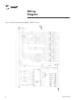
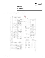
Страница 60: ...CGAD SVN02C EN 60 Wiring Diagram Fig 41 Power and command wiring diagram CGAD100 Part I...
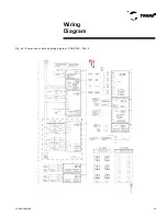
Страница 61: ...CGAD SVN02C EN 61 Wiring Diagram Fig 42 Power and command wiring diagram CGAD100 Part II...
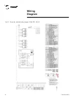
Страница 62: ...CGAD SVN02C EN 62 Wiring Diagram Fig 43 Power and command wiring diagram CGAD100 Part III...
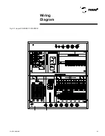
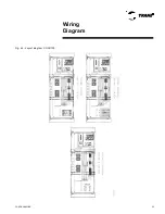
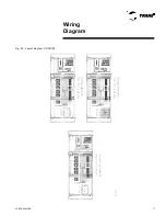
Страница 63: ...CGAD SVN02C EN 63 Wiring Diagram Fig 44 Layout diagram CGAD100...
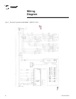
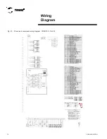
Страница 64: ...CGAD SVN02C EN 64 Wiring Diagram Fig 45 Power and command wiring diagram CGAD120 Part I...
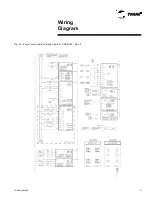
Страница 65: ...CGAD SVN02C EN 65 Wiring Diagram Fig 46 Power and command wiring diagram CGAD120 Part II...
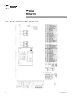
Страница 66: ...CGAD SVN02C EN 66 Wiring Diagram Fig 47 Power and command wiring diagram CGAD 120 Part III...
Страница 67: ...CGAD SVN02C EN 67 Wiring Diagram Fig 48 Layout diagram CGAD 120...
Страница 68: ...CGAD SVN02C EN 68 Wiring Diagram Fig 49 Power and command wiring diagram CGAD150 Part I...
Страница 69: ...CGAD SVN02C EN 69 Wiring Diagram Fig 50 Power and command wiring diagram CGAD150 Part II...
Страница 70: ...CGAD SVN02C EN 70 Wiring Diagram Fig 51 Power and command wiring diagram CGAD150 Part III...
Страница 71: ...CGAD SVN02C EN 71 Fig 52 Layout diagram CGAD150 Wiring Diagram...
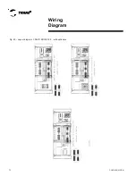
Страница 72: ...CGAD SVN02C EN 72 Wiring Diagram Fig 53 Layout diagram CGAD 100 125 150 with optionals...

