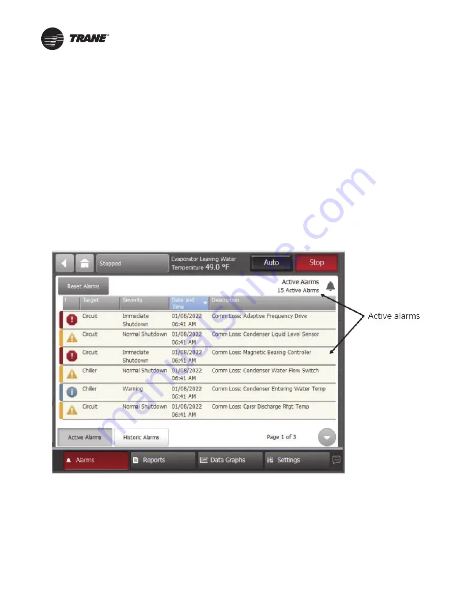
Trane Adaptive Frequency VFDB Скачать руководство пользователя страница 53

VFDB-SVX001A-EN

53 

Troubleshooting

Alarms

When an active alarm is present, it is identified in the 

Active 

Alarms


area in the upper left corner of the Tracer 

AdaptiView display. This serves two purposes. First to 
alert the operator that a alarm exists, and second to 
provide navigation to the Alarms list. 

Clicking on the active alarms causes the Alarms list to 
display. All active alarms are listed first and ordered by the 
alarm’s severity. The severity hierarchy is:

Immediate shutdown (highest priority and displays 
first)

Normal shutdown

Warning

Unknown (lowest priority and displays last)

Active alarms are followed by any historical alarms. These 
appear gray on the screen. The alarms button at the 
bottom of the screen flashes between two colors 
depending on the severity of the highest priority alarm 
(i.e., Immediate shutdown alarms cause the button to flash 
between red and black, and Normal shutdown alarms 
cause the button to flash between yellow and black).

Clicking directly on any of the active alarms links to a 
screen that explains the alarm and provides possible 
solutions.

You can also connect the laptop computer loaded with the 
Tracer TU service tool software directly to the Symbio 800 
controller to view the AFD last diagnostic code (refer to 

Table 6, p. 54

 for detailed information on which AFD 

settings you can see using Tracer TU).

Figure 41.

Tracer AdaptiView alarms screen

Содержание Adaptive Frequency VFDB

Страница 1: ...ualified personnel should install and service the equipment The installation starting up and servicing of heating ventilating and air conditioning equipment can be hazardous and requires specific knowledge and training Improperly installed adjusted or altered equipment by an unqualified person could result in death or serious injury When working on the equipment observe all precautions in the lite...

Страница 2: ...hazardous situation which if not avoided could result in minor or moderate injury It could also be used to alert against unsafe practices NOTICE Indicates a situation that could result in equipment or property damage only accidents WARNING Proper Field Wiring and Grounding Required Failure to follow code could result in death or serious injury All field wiring MUST be performed by qualified person...

Страница 3: ... trane com WARNING Follow EHS Policies Failure to follow instructions below could result in death or serious injury All Trane personnel must follow the company s Environmental Health and Safety EHS policies when performing work such as hot work electrical fall protection lockout tagout refrigerant handling etc Where local regulations are more stringent than these policies those regulations superse...

Страница 4: ... 33 Overhead Lifting 33 Lift the Power Module LV Control Cabinet 34 Lift Input Starter 35 Storage 35 Mechanical Installation 36 Install Drive panel 36 Connect Shipping Splits 36 Affix Cabinets to Floor 37 Install Input Starter 38 Anchoring 38 Load Cable Connections 39 Install Main Cooling Fans 40 Install the cooling fan for A frame drives 6 6 kV 40 Wiring 42 Input Power Input Starter to Drive Pane...

Страница 5: ...rFlex A or B Frame Pre Commis sioning Check List 1 Remote Mounted Medium Voltage Air Cooled Adaptive Frequency Drives PowerFlex 7000 Model AFDJ PowerFlex 6000T Model VFDB 1 Instructions 2 PowerFlex A or B Frame Pre Commis sioning Check List 3 ...

Страница 6: ...ult in death or serious injury Disconnect all electric power including remote disconnects before servicing Follow proper lockout tagout procedures to ensure the power can not be inadvertently energized Verify that no power is present with a voltmeter WARNING Hazardous Voltage w Capacitors Failure to follow instructions below could result in death or serious injury Disconnect all electric power inc...

Страница 7: ... applicable national and local and codes Service personnel must use proper PPE for servicing and must also use proper lockout tagout procedures during servicing lock the drive disconnect handle before servicing to prevent accidental pulling of disconnect handle at the drive panel In addition service personnel should disconnect the main supply disconnecting device upstream of the drive before perfo...

Страница 8: ...king on MV products and enhanced personal protective equipment PPE that is designed to mitigate the hazards of arc flash injuries are required for working on the products described in this literature Only medium voltage trained certified engineers are allowed to work on MV products NOTICE Equipment Damage Powering up equipment with an impaired condition as outlined below could cause equipment dama...

Страница 9: ... scheme is a cornerstone of the safety devices built into a product You are not authorized to work on and must refuse to work on any installed MV product where the key interlocks are missing damaged or compromised in any way Keys can never be duplicated without the owner of the product signing a waiver Service personnel should never be in possession of their own duplicate keys Match the personal p...

Страница 10: ...nfirm the tool is working properly prior to verifying de energization The PPE for medium voltage safety can only be removed once the MV power de energization is verifiedand confirmed The PPEfor control voltage can only be removed once the control voltage de energization is verified WARNING Hazardous Voltage w Capacitors Failure to follow instructions below could result in death or serious injury D...

Страница 11: ... Rockwell office Back feed power caused by a fan that rotates from ambient wind blowing on it electric motor s rotating when equipment manually moves it and other potential sources of back feed power may be downstream from the MV cabinet Identify sources of potential back feed power downstream from the MV cabinet Prevent back feed power by locking blocking or by other measures to positively contro...

Страница 12: ...ng For information regarding the servicing of drive components please refer to the appropriate Rockwell literature that ships with the drive Service Information This equipment should be installed adjusted and serviced by qualified electrical maintenance personnel who are familiar with the construction and operation of the equipment and the hazards involved as defined in the National Electrical Cod...

Страница 13: ...tion to drive and terminate X Line 3 phase voltage to drive be sure to do this before fan shroud installation A Frame only Fan 3 phase voltage to drive B Frame Drive to motor power wiring Control power drive to chiller interconnect LV Install fan shroud boxes X Install resistor box X Provide adequate ventilation for heat rejection of drive X Precommision chiller refer to chiller IOM forms X Fill o...

Страница 14: ...ium voltage compartments Mechanical and electrical interlocks between the drive and input disconnecting means Double offset ventilation pattern on the drive doors to ensure operator safety Input Voltage Tolerance 10 of Nominal Line Voltage Input Frequency 50 60 Hz 10 Output Voltage Rating 0 2300 0 3300 0 4160 0 6600 Input Protection Distribution Class Heavy Duty Surge Arrestors Control Method Sens...

Страница 15: ...it 5 6 7 8 Starter Size Use Rated Load Amps RLA value Digit 9 Unit Line Voltage K 2300V 60Hz 3Ph L 2400V 60Hz 3Ph N 4160V 60Hz 3Ph P 3300V 60Hz 3Ph X 6600V 60Hz 3 Ph V 3300V 50Hz 3Ph Z 6600V 50Hz 3 Ph S Special Digit 10 11 Design Sequence A0 First Design Digit 12 Starter Type B Remote Mounted Digit 13 Agency Listing 0 UL and CUL Listed Standard on All Units 1 CE Digit 14 Special Options 0 None S S...

Страница 16: ...z 160 700 71310 400 AWG 6 6KV phase 400 AWG 6 6KV phase 400 AWG 6 6KV phase 11880 C 216 2300 2400V 60Hz 215 900 92470 11880 C 77 3300V 50 60Hz 77 422 47770 400 AWG 6 6KV phase 400 AWG 6 6KV phase 400 AWG 6 6KV phase 8360 B 118 3300V 50 60Hz 118 671 68580 8360 B 141 3300V 50 60Hz 140 805 81210 8360 B 186 3300V 50 60Hz 186 1073 103050 11880 C 216 3300V 50 60Hz 215 1207 117380 11880 C 39 4160V 60Hz 4...

Страница 17: ...igned for non shielded cable or shielded cable with prefabricated stress cones 5 Maximum cable information refer to Table 2 and Table 3 Shipping Note Mounted on a 500 lb 226 8 kg max wooden skid with provisions for a fork truck Lifting means also supplied on top Table 3 B Frame weights a and heat rejection SRRL LINE VOLTAGE FREQUENCY VFD AMPS Motor HP MAX HEAT REJECTION BTU HR MAX NUMBER AND SIZE ...

Страница 18: ...NE CABLE CONDUIT OPENING LOAD CABLE CONDUIT OPENING 17 1X11 8 CONTROL WIRE CONDUIT OPENING 3 93X3 93 LINE CABLE CONDUIT OPENING LOAD CABLE CONDUIT OPENING 17 1X11 8 CONTROL WIRE CONDUIT OPENING 3 93X3 93 A B 11 71 44 21 5 02 8 96 49 21 59 1 LINE CABLE CONDUIT OPENING LOAD CABLE CONDUIT OPENING 17 1X11 8 CONTROL WIRE CONDUIT OPENING 3 93X3 93 C ...

Страница 19: ...02 19 64 45 45 5 31 50 80 59 1 11 81 11 81 LINE CABLE CONDUIT OPENING 9 84X7 87 LOAD CABLE CONDUIT OPENING 9 84X7 87 SERVICE CUT OUT 5 51X17 72 CONTROL WIRE CONDUIT OPENING 3 94X4 92 LINE CABLE CONDUIT OPENING 9 84X7 87 LOAD CABLE CONDUIT OPENING 9 84X7 87 SERVICE CUT OUT 5 51X17 72 CONTROL WIRE CONDUIT OPENING 3 94X4 92 A B ...

Страница 20: ...DB SVX001A EN Figure 4 A Frame Front view VFD 2300 3300 4160V in 47 64 18 51 91 65 63 39 15 75 5 9 5 9 91 65 22 05 15 75 DISPLAY HAZARDOUS VOLTAGE LABEL T1 T2 T3 1U 1V 1W GROUND BAR 91 65 75 20 5 9 22 05 15 75 A B C ...

Страница 21: ...Cabinet VFDB SVX001A EN 21 Figure 5 A Frame Front view VFD 6600V in 15 75 21 54 90 94 5 9 15 75 21 54 91 65 110 04 5 9 91 65 87 01 GROUND BAR DISPLAY HAZARDOUS VOLTAGE LABEL T1 T2 T3 1U 1V 1W A B ...

Страница 22: ...INE CABLE CONDUIT OPENING LOAD CABLE CONDUIT OPENING 8 66X5 63 CONTROL WIRE CONDUIT OPENING 3 93X3 93 MOUNTING HOLES FOR 0 72 18 DIA ANCHOR BOLTS B LINE CABLE CONDUIT OPENING LOAD CABLE CONDUIT OPENING 8 66X5 63 CONTROL WIRE CONDUIT OPENING 3 93X3 93 MOUNTING HOLES FOR 0 72 18 DIA ANCHOR BOLTS C LINE CABLE CONDUIT OPENING LOAD CABLE CONDUIT OPENING 8 66X5 63 CONTROL WIRE CONDUIT OPENING 3 93X3 93 ...

Страница 23: ...13 47 20 47 20 49 21 23 62 45 47 67 32 87 01 33 46 B A CONTROL WIRE CONDUIT OPENING 3 94X4 13 LINE CABLE CONDUIT OPENING 15 75X5 51 LOAD CABLE CONDUIT OPENING 15 75X5 51 MOUNTING HOLES FOR 0 71 18 0 DIA ANCHOR BOLTS CONTROL WIRE CONDUIT OPENING 3 94X4 13 LINE CABLE CONDUIT OPENING 15 75X5 51 LOAD CABLE CONDUIT OPENING 15 75X5 51 MOUNTING HOLES FOR 0 71 18 0 DIA ANCHOR BOLTS ...

Страница 24: ... 8 A Frame Door swing requirements in 90 MAX DOOR SWING 90 MAX DOOR SWING 90 MAX DOOR SWING H MAX 90 MAX DOOR SWING 90 MAX DOOR SWING 90 MAX DOOR SWING 90 MAX DOOR SWING 34 73 MAX DOOR OPENING DOOR OPENING VFD 6600V VFD 2300 3300 4160V ...

Страница 25: ...Cabinet VFDB SVX001A EN 25 Figure 9 A Frame Interior view major components in ...

Страница 26: ...2 91 55 12 140 94 143 70 59 1 59 1 55 12 47 05 6 30 47 05 6 30 62 99 62 99 CONTROL WIRE CONDUIT OPENING 5 4X5 4 LINE CABLE CONDUIT OPENING 5 4X5 4 LOAD CABLE CONDUIT OPENING 5 4X5 4 CONTROL WIRE CONDUIT OPENING 5 4X5 4 LINE CABLE CONDUIT OPENING 5 4X5 4 LOAD CABLE CONDUIT OPENING 5 4X5 4 A B ...

Страница 27: ...Cabinet VFDB SVX001A EN 27 Figure 11 B Frame Front view in 161 42 91 65 18 50 5 9 15 75 149 61 18 50 15 75 5 9 91 65 1U 1V 1W T1 T2 T3 DISPLAY HAZARDOUS VOLTAGE LABEL GROUND BAR A B ...

Страница 28: ...8 54 58 07 85 35 1 26 31 48 61 69 1 26 33 23 65 20 97 08 96 96 B CONTROL WIRE CONDUIT OPENING 5 4X5 4 LINE CABLE CONDUIT OPENING 5 4X5 4 LOAD CABLE CONDUIT OPENING 5 4X5 4 MOUNTING HOLES FOR 0 72 18 DIA ANCHOR BOLTS A CONTROL WIRE CONDUIT OPENING 5 4X5 4 LINE CABLE CONDUIT OPENING 5 4X5 4 LOAD CABLE CONDUIT OPENING 5 4X5 4 MOUNTING HOLES FOR 0 72 18 DIA ANCHOR BOLTS ...

Страница 29: ...re 13 B Frame Door swing requirements in 90 0 MAX DOOR SWING 90 0 MAX DOOR SWING 90 0 MAX DOOR SWING 90 0 MAX DOOR SWING 90 0 MAX DOOR SWING 90 0 MAX DOOR SWING 39 45 MAX DOOR OPENING Figure 14 B Frame Interior view major components ...

Страница 30: ...2 30 00 16 04 4 64 LINE CABLE CONDUIT OPENING 5 68X9 00 5 68X9 00 CONDUIT OPENING LOAD CABLE CONTROL WIRE CONDUIT OPENING 3 00X3 00 Figure 16 Input starter Front view in 2 48 90 24 98 25 98 COPPER ONLY LABLE 1U 1V 1W L1 L2 L3 GND 1 00 25 0 x3 00 76 0 NON REMOVABLE SILL CHANNELS ...

Страница 31: ...0 25 98 9 29 30 00 20 12 4 45 23 68 32 95 LINE CABLE CONDUIT OPENING 5 68X9 00 CONTROL WIRE CONDUIT OPENING 3 00X5 00 LOAD CABLE CONDUIT OPENING 5 68X9 00 MOUNTING HOLES FOR 0 50 12 0 DIA ANCHOR BOLTS Figure 18 Input starter Door swing requirements in 90 MAX DOOR SWING 23 5 MAX DOOR OPENING ...

Страница 32: ...Cabinet 32 VFDB SVX001A EN Figure 19 Input starter Interior view major components ...

Страница 33: ...r than the cabinet weight Lift the cabinet using the overhead lifting angles or isolation transformer lifting provisions and suitable spreader bars and rigging attached to the fork lift Important Do not allow the drive to tilt during lifts and or moves Drives may contain heavy components that are mounted for vertical shift Tilting can cause heavy items to shift Figure 20 Crated cabinet WARNING Imp...

Страница 34: ...ether to prevent separation and damage while riggers move the drive to the final installation area 1 Remove the lifting angles from the skid 2 Align and secure the lifting angles in four places as shown in below figure Lift the Isolation Transformer Cabinet for B frame Drives Only 1 Unfastenand remove the middle top plate on top of the cabinet and retain middle top plate and hardware The configura...

Страница 35: ...s like power supplies power cells etc is stored unpowered under normal storage temperatures and conditions it can be kept up to 15 years Storage the drive in a dry clean and cool area The storage temperature must be maintained between 40 70 C 40 158 F This temperature rating applies only to the drive it does not include the UPS Uninterruptible Power Supply If the storage temperature fluctuates sig...

Страница 36: ...er 2 Align the cabinet side sheets together at the holes for the hardware refer to below figure 3 Secure the cabinets together using M6 and M8 hardware Open the doors to access front edge joining holes four or five places Figure 26 Align the cabinets B frame 6 kV shown Isolation Transformer Cabinet Power Module LV Control Cabinet Table 1 Sidesheet Openings Front Wireway U Phase Motor Cable V Phase...

Страница 37: ...000 mm See Mounting Requirements in the PowerFlex 6000T Drives Shipping and Handling Manual publication 6000 PC100 for further information on the steel base and desired trench and mounting customer specifications Figure 27 Secure the cabinets B frame Secure with M6 hardware 8 places 2 socket screw M6x16 Combination pillar WARNING Drive Mounting Instructions Failure to correctly anchor the cabinet ...

Страница 38: ...voltage panel to the front and left of cabinet Refer to above figure Note The power cell door must be in a fully opened position prior to rotating the low voltage panel 7 Locate the removable bus access barrier 2 8 Remove retaining screws from removable bus access barriers to expose incoming cable connections to main bus Refer to below figure 9 Install incoming line cables to power bus 10 Reverse ...

Страница 39: ...re 17 p 31 Figure 33 p 39 and Figure 34 p 40 The plate may be punched or cut to mount conduit 3 Load cables for the power cell should be routed before control cables Pull the cables into the cabinet through the appropriate opening refer to Figure 15 p 30 Figure 17 p 31 Figure 33 p 39 and Figure 34 p 40 4 Remove current transformer barriers 5 Connect the cables to the current transformers and tight...

Страница 40: ...ooling fan for A frame drives 6 6 kV To install the cooling fan for A frame 6 6 6 kV drives follow these instructions 1 Place the fan housing on the top plate of the drive and slide the fan housing back Verify that the back flange ofthefan housingslides underthe topplatefan bracket assembly 2 Secure the fan housing using M6 hardware across the front of the fan assembly 3 Connect fan wiring to fan ...

Страница 41: ...41 Figure 36 Main cooling fan housing A frame 6 6 6 kV Back flange of fan Fan wiring terminals located behind this cover Mount fan assembly with M6 hardware across the front of the fan assembly Top plate bracket assembly Front View Back View ...

Страница 42: ...e phase input power leads to circuit breaker terminals L1 L2 and L3 Tighten these connections to 30 ft lb 40 7 N m Use only copper conductors for the input power leads Input power wiring shouldbe copper and should be sized according to applicable codes to handle the drive s continuous rated input current Table 4 Wire sizing reference AWG MCM mm2 equivalent 22 0 32 21 0 35 20 0 5 18 0 75 17 1 0 16 ...

Страница 43: ...the National Electrical Code NEC the National Fire Protection Association NFPA or the Canadian Electrical Code CEC as applicable and other appropriate local codes Refer to controller and motor nameplates for electrical data Important Before servicing disconnect all power sources and allow at least 20 minutes for capacitors to discharge All electrical enclosures unit or remote are IP2X Grounding th...

Страница 44: ...Wiring 44 VFDB SVX001A EN Figure 37 Motor terminal connection MEDIUM VOLTAGE 2300 13800V RATR RPIR RXL CSOL CATR CPIR CXL OR CVAC ...

Страница 45: ...er 3 Cross power wiring 4 Chiller control power 5 HPC Interlock For medium voltage drives Dry contact 14 AWG max wire size 6 Oil pump interlock 7 Jumper required or remote stop switch 8 Chiller to drive communication link 9 Cross control wiring a For AWG MCM equivalents in mm2 refer to Table 4 p 42 4 1 2 3 5 6 7 8 9 ...

Страница 46: ... Figure 39 Chiller and PowerFlex 6000T remote configuration Motor to Drive Line Vac Supply CPTR power or 120V HPC oil pump interlock Modbus Input Starter Drive Panel Figure 40 PowerFlex 6000T Scope of input voltages to from drive Line Supply Line Supply To Motor PowerFlex 6000T Frame A PowerFlex 6000T Frame B To Motor Oil pump Modbus HPC Oil pump Modbus HPC Input Starters Input Starter Drive Panel...

Страница 47: ...T1 T2 to T2 T3 to T3 3 Cross power wiring between input starter and drive panel 1U to 1U 1V to 1V 1W to 1W 4 Chiller Control power Chiller control power can be supplied at 115 Vac if without the CPTR transformer or at a specified voltage if the step down transformer CPTR is specified Models CDHF CDHG CVHE CVHF and CVHG 4a Without CPTR Connect 115 Vac 40 amps 4 kVA L1 to 1X1 1 Wire 1A L2 to 1X1 12 ...

Страница 48: ...rol and power wiring separately The distance between the control cable tray and power cable tray must be 11 8 in 300 mm minimum Do NOT mix AC and DC wires within the same cable bundle 8 Communications 3 wire Modbus communication link Models CDHF CDHG CVHE CVHF and CVHG 1X3 1 to terminal 8 Black 1X3 2 to terminal 3 White 1X3 3 to terminal 7 Green Shield Ground one end at drive end only Models CDHH ...

Страница 49: ...nnected properly 7 Re verify control wiring from any external control devices 8 Confirm cooling system is operational 9 Verification of proper phasing from input voltage source to drive 10 Confirm cabling of drive to motor isolation transformer and line feed 11 Collect test reports indicating megger hi pot test has been performed on line and motor cables 12 Control power checks to verify all syste...

Страница 50: ... Type Remote Mount Comm AFD VFDB Tracer TU Configuration View Starter Trane Default Setting Volts and Hz Amps Unit Line Voltage Motor Data Motor NP RLA Manufacturer Motor NP Power Type and Frame RTD Type see order Drawing Must be set per sales order variable Serial Number Test Log Date Log 1 Log 2 Nameplate Data Tracer TU Unit Status View AFD RLA AFD Input Frequency KW AFD Average Input Current Vo...

Страница 51: ... depends on the amount of dust in the environment Annual Maintenance As the name implies these maintenance tasks should be performed on an annual basis by a qualified MV drive technician These are recommended tasks and depending on the installation conditions and operating conditions you may find that the interval can be lengthened Initial Information Gathering by Qualified MV Drive Technician Con...

Страница 52: ...ature or contamination Clean all contaminated components using a vacuum cleaner DO NOT use a blower and wipe clean components where appropriate Conductthephysicalinspectionandverificationforthe proper operation of the contractor isolator interlocks and door interlocks Conductthephysicalinspectionandverificationforthe proper operation of the key interlocks Conduct the cleaning of the fans and verif...

Страница 53: ...ive alarms are followed by any historical alarms These appear gray on the screen The alarms button at the bottom of the screen flashes between two colors depending on the severity of the highest priority alarm i e Immediate shutdownalarms cause the button to flash between red and black and Normal shutdown alarms cause the button to flash between yellow and black Clicking directly on any of the act...

Страница 54: ... service group for additional support if necessary Table 6 IOM Tracer AdaptiView and drive diagnostics Chiller Tracer AdaptiView Diagnostic MV Drive Diagnostic Drive Fault AFD Bus Over Voltage OverVoltage 10107 AFD Bus Under Voltage UnderVoltage 10106 AFD Bus Under Voltage DC Bus Under Vltg 10209 AFD Bus Under Voltage U0 U8_DCBusUnderVltg 12510 AFD Bus Under Voltage U0 U8_DCBusUnderVltg 12511 AFD ...

Страница 55: ...put PhaseLoss 10008 AFD Precharge Fault Bus Rate of Rise 13075 AFD Precharge Fault PrchrgDvcFailCls 188 Table 6 IOM Tracer AdaptiView and drive diagnostics continued Chiller Tracer AdaptiView Diagnostic MV Drive Diagnostic Drive Fault AFD Precharge Fault PrchrgDvcFailOpn 189 AFD Precharge Fault PrchrgDvcMismatch 192 AFD Precharge Fault PrchrgDvc CfgErr 288 AFD Over Temperature Powercell Transfomer...

Страница 56: ...l Transfomer Over Temperature 14247 AFD Over Temperature Powercell Transfomer Over Temperature 14249 AFD General Failure All other faults AFD Gate Kill active Table 6 IOM Tracer AdaptiView and drive diagnostics continued Chiller Tracer AdaptiView Diagnostic MV Drive Diagnostic Drive Fault LED Color Indication Gateway Status Refer to the user manual for further details Processing Green Processing m...

Страница 57: ...for the job being undertaken could result in death or serious injury Technicians in order to protect themselves from potential electrical mechanical and chemical hazards MUST follow precautions in this manual and on the tags stickers and labels as well as the instructions below Before installing servicing this unit technicians MUST put on all PPE required for the work being undertaken Examples cut...

Страница 58: ...st fax or e mail to the appropriate regional Rockwell and Trane office Once all points of the check list are complete initial each check box and provide the date It will be necessary to review this with the electrician or electrical contractor Photocopy the check list and fax the copy to the Medium Voltage Center of Expertise MVCOE and to Trane Technical support along with the planned start up dat...

Страница 59: ...der Number __________________________________________________________________ MV Drive Serial Number _________________________________________________________________________ Rockwell GMS Service Engineer Requested YES _____________________________________________________ Scheduled Commissioning Date a _________________________________________________________________ a Important The average start ...

Страница 60: ...EC regulations and or local regulations Note To be completed by Electrical Contractor If the drive has an isolation transformer the transformer enclosure and or frame must be bonded to system ground at a minimum of two locations If the drive has an isolation transformer the wye secondary neutral point must not be grounded If shipping splits exist in the line up the ground bus between cabinets has ...

Страница 61: ... both ends If shielded MV cables are spliced the shield must remain continuous and insulated from ground All wire sizes used are selected by observing all applicable safety and CEC NEC IEC regulations All power connections are torqued as per Rockwell Automation Specifications refer to the Torque Requirements listed in Table 7 p 2 All customer power cabling has been Meggered or Hi Pot tested before...

Страница 62: ...are committed to using environmentally conscious print practices Trane by Trane Technologies NYSE TT a global climate innovator creates comfortable energy efficient indoor environments for commercial and residential applications For more information please visit trane com or tranetechnologies com AFDJ ADF001C EN 07 May 2022 Supersedes AFDJ ADF001B EN May 2020 ...

Страница 63: ...Notes VFDB SVX001A EN 63 ...

Страница 64: ...thout notice We are committed to using environmentally conscious print practices Trane by Trane Technologies NYSE TT a global climate innovator creates comfortable energy efficient indoor environments for commercial and residential applications For more information please visit trane com or tranetechnologies com VFDB SVX001A EN 07 May 2022 NEW ...

Отзывы: