- 16 -
tousek
/ EN_REX-Force_01 / 25. 03. 2020
The stop input has no emergency stop function! - In order to ensure the emergency stop function, provide
the supply line with an all-pole disconnecting emergency stop switch, that locks after actuation!
Attention
During connection, adjustment and maintenance works please take care, that the electronic circuit board won´t be
damaged by moisture (rain).
Fault message contact and signaling
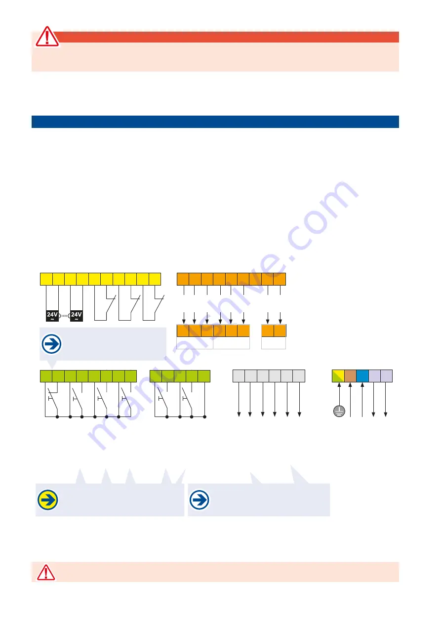
contact: Potential-free contacts, max.
switching voltage 60Vdc, 30W ohmic load
The impulse inputs (pulse, I loop, pedes-
trian door, CLOSE, OPEN) are
not active
when in the traffic light mode!
grounding
power supply
230V a.c
.
to
flashing
light
module
input
230V
a.c., 100W
30 31 30 32 30 33 30 34
94 95 76 77 78 79
41 42 43 44 45 46 45 48 45 49
If no STOP button is connected,
bridge the terminals 30/31
(jumper as factory settings).
0 1
2
10 11
24Va.c. supply
photocell
PHC-transmitter
PHC-receiver
PHC-contact inside
PHC-contact outside
PHC-contact back area
common
ST
OP-button
common
IMPULSE-button
common
CLOSE-button
common
pedestrian switch
Fault message
contact
flasging light
12Vd.c., max. 5W
signal contact
(I-loop)
common
IMPULSE
OPEN
common
Induction loop
common
High
High
High
Low
Low
Low
shield
shield
84 85 86 84 85 86 87
84 85 86
84 85 86
88 89
88 89
ST REX smart1
Traffic light
control unit
Bus system
Bus system
ST REX smart2
STA 11
30 36 30 39 30
3.3 Terminal assignment ST REX (Z1)
REX Force


