


User Manual for Machine Vision Cameras
110
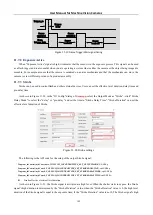
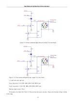
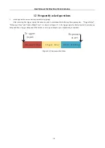
Figure 11
-
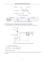
36
Non
-
isolated input, output I/ O circuit
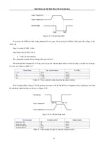
1, GPI2 input level parameter:
Logic 0 input level: 0
-
0.9 VDC (DIR _ GPI pin)
Logic 1 input level: 1~20VDC (DIR_GPI pin)
Figure 11
-
37
Input logic level
To prevent damage to the GPI pin, connect the GND pin before entering voltage to the DIR_GPI pin.
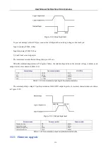
2, GPO2 output level parameter:
The maximum current allowed through this pin is 25 mA.
When the ambient temperature is 25 degrees Celsius, the relationships between the external voltage, resistance and
output low level are shown in Table 11
External voltage
Non-essential resistance
VL(GPO2)
3.3V
1KΩ
0V
5V
1KΩ
0V
12V
2.4KΩ
0V
24V
4.7KΩ
0V
Table 11
-
5
Non
-
isolated output logic’s low level parameters
The external pull
-
up voltage 5V pull
-
up resistance 1K Ω, GPO2 output logic level, electrical characteristics are shown
in Figure 11
38 and Table 11
6 respectively.