


User Manual for Machine Vision Cameras
111
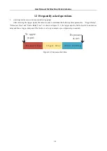
Figure 11
-
38
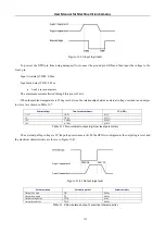
Output logic level
Parameter name
Parameter symbol
Parameter values
Output rise time
TR
0.01us
Output downtime
TF
0.01us
Output rising delay
TDR
0.02us
Output drop delay
TDF
0.04us
Table 11
-
6
Non
-
isolated output’s electrical characteristics
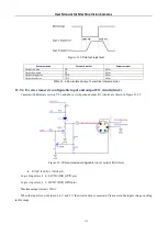
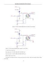
11.9.4
I3 series camera’s configurable input and output I/O circuits(line2)
Camera with hardware version V2.0 and above, its input and output I/O circuits are shown in Figure 11
Figure 11
-
39
Non
-
isolated configurable input / output I/O circuits
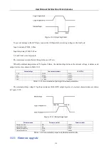
•
Line2 is set as input pin
Logic 0 input level: 0~0.6VDC (DIR_GPIO pin)
Logic 1 input level: 2~24VDC (DIR_GPIO pin)
Maximum input current: 25mA
When the input level is between 0.6 V and 2 V, the circuit action is uncertain. Please avoid the input voltage working
in this range.