


User Manual for Machine Vision Cameras
96
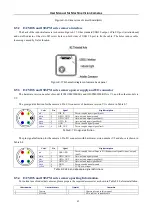
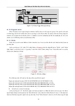
Under the trigger mode, trigger signal source is either from software trigger, or from external trigger. The external
trigger signal is from either the pin isolated by opto
-
coupler or the non
-
isolated pin.
The following is the API code for the setup of the trigger source:
// Trigger Source: 0
-
> line0 , 1
-
> line2 , 2
-
> line3 , 3
-
> Counter , 4
-
> PWM , 5
-
> Software
Toupcam_IoControl(m_hCam, 0, TOUPCAM_IOCONTROLTYPE_SET_TRIGGERSOURCE, val, NULL);
⚫
Software trigger
The camera supports software trigger mode. When a software trigger is executed, the client software will send the
command through USB3.0 to activate the camera to acquire and transmit images.
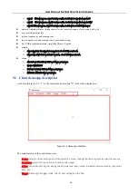
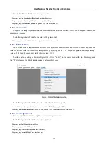
As shown in Figure 11
7, in
democpp
, first click "Enter Trigger Mode" to enter trigger mode. Click "Set trigger
Number" to define the number of triggers and finally click "Trigger" and the software will receive the number of triggers. If
you click "Loop Trigger", you will enter a continuous trigger mode and clicking it again will exit the current trigger mode.
Figure 11
-
7
Software trigger setup
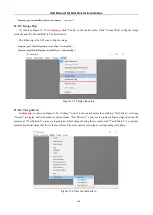
⚫
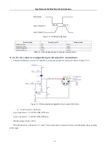
External trigger
(For I3 series only )The camera has an opto
-
isolated input line “Opt_in” on the hardware and a direct GPI input line
(the hardware version number V2.0 and above is configurable GPIO port). The user can select either line as the trigger
source. Counter mode and PWM mode are also provided.