


User Manual for Machine Vision Cameras
99
Toupcam_IoControl(m_hCam, 0, TOUPCAM_IOCONTROLTYPE_SET_TRIGGERSOURCE, 3, NULL);
//Counter Source: 0
-
> line0 , 1
-
> line2 , 2
-
> line3
Toupcam_IoControl(m_hCam, 0, TOUPCAM_IOCONTROLTYPE_SET_COUNTERSOURCE, val, NULL);
Toupcam_IoControl(m_hCam, 0, TOUPCAM_IOCONTROLTYPE_SET_COUNTERVALUE, val, NULL);
11.4.6
PWM trigger mode
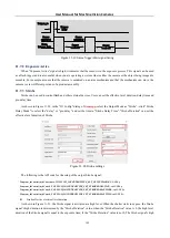
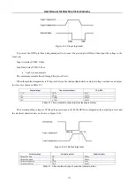
The camera provides Pulse Width Modulation (PWM) trigger mode, which controls exposure time by pulse width.
The main difference between this mode and the standard single frame trigger mode is the exposure method. The exposure
time per frame is determined by the trigger pulse width, as shown in Figure 11
Trigger_in1
Trigger_in2
Trigger_in3
Sensor
exposure1
Sensor
exposure2
Sensor
exposure3
Debounce
time
Debounce
time
Debounce
time
t1
t1
t2
t2
t3
t3
Figure 11
-
13
PWM mode timing
The following cameras with rolling shutter sensors do not support PWM trigger mode
:
IUA6300KMA, IUA6300KPA; IUA20000KMA, IUA20000KPA;
IUB4200KMA, IUB4200KMB;
IUC26000KPA, IUC60000KMA, IUC60000KPA;
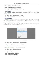
As shown in Figure 11
14 in
democpp
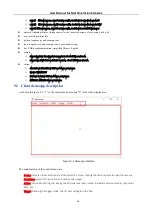
, select the trigger source as PWM, under "Trigger Source" and click "PWM
Source" to select the external trigger source for input.
The following is the API code for the setup of the counter trigger mode:
Toupcam_IoControl(m_hCam, 0, TOUPCAM_IOCONTROLTYPE_SET_TRIGGERSOURCE, 4, NULL);
Toupcam_IoControl(m_hCam, 0, TOUPCAM_IOCONTROLTYPE_SET_PWMSOURCE, val, NULL);