


User Manual for Machine Vision Cameras
108
The following is the API code for the setup of the test pattern:
// TestPattern: 0
-
> TestPattern Off , 3
-
> Moving Diagonal Gray Gradient , 5
-
> Moving Vertical Gray Gradient , 7
-
> Moving Horizontal Gray
Gradient , 9
-
> Moving Diagonal Chromatic Gradient
Toupcam_put_Option(m_hCam, TOUPCAM_OPTION_TESTPATTERN, val);
11.9
I3 series camera’s I/ O electrical properties
11.9.1
I3 series camera’s opto
-
isolated input circuit (line0)
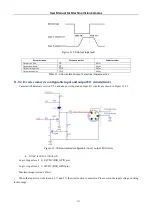
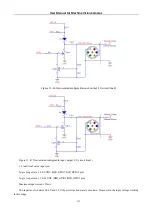
In the camera I/O control, opto
-
isolated input circuit is shown in Figure 11
Figure 11
-
32
Opto
-
isolated input circuit
Logic 0 input level: 0~1.4VDC (OPTO_IN pin)
Logic 1 input level: 2.2~24VDC (OPTO_IN pin)
Maximum input current: 30mA
The input level is between 1.4V and 2.2V, the circuit action state is uncertain, please avoid the input voltage working
in this range.
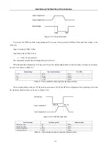
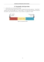
Figure 11
-
33
Input logic level
Input rise delay (TDR): 5us
Input drop delay (TDF): 25us
11.9.2
I3 series camera’s opto
-
isolated output circuit(line1)
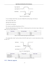
In camera I/O control, opto
-
isolated output circuit is shown in Figure 11