


User Manual for Machine Vision Cameras
109
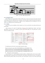
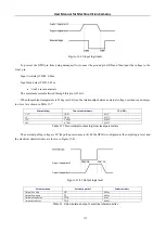
Figure 11
-
34
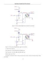
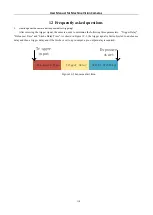
Opto
-
isolated output circuit
Opto
-
isolated output maximum current: 30mA
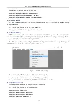
Figure 11
-
35
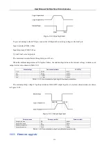
Output logic level
The electrical characteristics of the opto
-
isolated output signal (external voltage 5V, external resistor 1K) are shown in
Parameter name
Parameter symbol
Parameter values
Output logic low level
VL
760mV
Output logic high
VH
5V
output rise time
TR
8.6us
Output downtime
TF
2.2us
Output rising delay
TDR
17.5us
Output drop delay
TDF
4.2us
Table 11
-
3
Opto
-
isolated output signal’s electrical characteristics
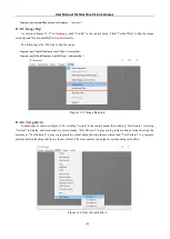
The corresponding current and output logic low level parameters are shown in Table 11
4 when different voltage and
resistors are used in external circuit.
External voltage
Non-essential resistance
VL
Output current
3.3V
1KΩ
668mV
2.82mA
5V
1KΩ
760mV
4.31mA
12V
2.4KΩ
798mV
4.68mA
24V
4.7KΩ
833mV
4.97mA
Table 11
-
4
Opto
-
isolated output logic’s low level parameters
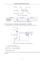
11.9.3
I3 series camera’s input and output I/O circuit(line2/line3)
In camera I/O control with hardware version number V1.0, non
-
isolated input, output I/O circuit is shown in Figure