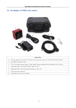


User Manual for Machine Vision Cameras
28
3.14
IUA5000KMA
Model
Parameter
IUA5000KMA
5.0M pixels 2/3” CMOS
USB3.0 industrial camera
Camera
Sensor model
Sony IMX264LLR
Pixel size
3.45 µm×3.45 µm
Sensor size
2/3”
Frame rate
35.6fps@2448×2048
、
87.6fps@1224×1024
Dynamic range
73.6dB
Signal
-
to
-
Noise ratio
40.4dB
Sensitivity
71%@575nm
Peak QE
1830mV
Dark current
0.15mV
Gain range
1x
-
50x
Exposure time
15µs
-
15sec
Shutter
Global shutter
Binning
Hardware 2x2; Software 2x2, 3x3, 4x4
Data interface
USB3.0 (USB3.1 GEN1)
Digital I/O
One optical
-
coupling isolated input, one optical
-
coupling isolated output, two non
-
isolated input and output
Data format
RAW8/RAW12/RGB8/RGB24/RGB32/RGB48
General specification
Power supply
Power with USB3.0/ DC12V
Power consumption
<3.6W
Temperature
Working temperature
-
10~50
℃
, storage temperature
-
30~70
℃
Humidity
20%
-
80%, no condensation
Size
68mmx68mmx28.1mm
Weight
219g
Lens mount
C
-
mount
Software
ToupView/ SDK
Operating system
Win32/WinRT/Linux/macOS/Android
Certification
CE, FCC, RoHS
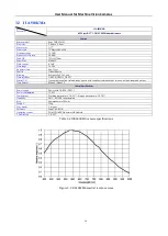
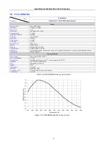
Table 3
-
14 IUA5000KMA camera specifications
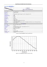
Figure 3
-
14
IUA5000KMA spectral response curve