710CDT/720CDT
4-47
4.16 FL Inverter Board
Removing the FL Inverter Board
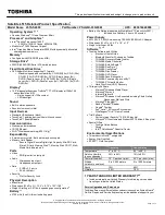
To remove the FL inverter board, follow the steps below and refer to Figure 4-45.
1.
Turn off the power to the computer, then disconnect the AC adapter and all external
cables connected to the computer.
2.
Remove the battery pack, optional memory module, optional PC card, and display
mask as described in Sections 4.2, 4.3, 4.4, and 4.15.
3.
Remove
two M2.5x6 screws
securing the
FL inverter board
.
4.
Carefully rotate the
FL inverter board
out from right to left and disconnect the
input cable
from
CN1
and the
HV cable
from
CN2
.
Note
: You may wish to place a binder and form pad under the display to
provide additional stability while performing these steps.
Figure 4-45 Removing the FL inverter board
Содержание Tecra 710CDT
Страница 186: ...710CDT 720CDT B 1 Appendix B Board Layouts B 1 System Board Front View Figure B 1 System board layout front ...
Страница 187: ...B 2 710CDT 720CDT B 2 System Board Back View Figure B 2 System board layout back ...
Страница 207: ...C 16 710CDT 720CDT ...
Страница 215: ...E 2 710CDT 720CDT E 3 German GR Keyboard Figure E 3 GR keyboard E 4 French FR Keyboard Figure E 4 FR keyboard ...
Страница 216: ...710CDT 720CDT E 3 E 5 Spanish SP Keyboard Figure E 5 SP keyboard E 6 Italian IT Keyboard Figure E 6 IT keyboard ...
Страница 221: ...G 2 710CDT 720CDT ...
Страница 222: ...710CDT 720CDT G 3 ...