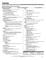
710CDT/720CDT
4-29
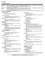
8.
Disconnect the
membrane switch cable
from
PJ701
on the
IPS board
. Be careful
when disconnecting the cable as it only releases approximately
1-2mm. Gently release it from its pressure plate.
9.
Disconnect the
FL inverter cable
from
PJ703
on the IPS board.
10.
Disconnect the
microphone
cable
from
PJ207
on the jack board.
11.
Remove
one M2.5x6 screw
securing the
ground cable
to the computer. This screw
is somewhat hidden under the FL Inverter cable near the right hinge.
Figure 4-27 Removing cables
12.
Remove the
volume control knob
.
13.
Release
nine latches
securing the keyboard base: three on the right, two in front,
and four on the left.
14.
Lift up the
keyboard base
and
display assembly
so you can disconnect the
display
sensor cable
from
PJ705
on the
IPS board
. The narrow strings at the sides of the
keyboard base can be easily broken, so be careful when handling them.
Содержание Tecra 710CDT
Страница 186: ...710CDT 720CDT B 1 Appendix B Board Layouts B 1 System Board Front View Figure B 1 System board layout front ...
Страница 187: ...B 2 710CDT 720CDT B 2 System Board Back View Figure B 2 System board layout back ...
Страница 207: ...C 16 710CDT 720CDT ...
Страница 215: ...E 2 710CDT 720CDT E 3 German GR Keyboard Figure E 3 GR keyboard E 4 French FR Keyboard Figure E 4 FR keyboard ...
Страница 216: ...710CDT 720CDT E 3 E 5 Spanish SP Keyboard Figure E 5 SP keyboard E 6 Italian IT Keyboard Figure E 6 IT keyboard ...
Страница 221: ...G 2 710CDT 720CDT ...
Страница 222: ...710CDT 720CDT G 3 ...