2 Troubleshooting
2.5 2.5-inch HDD
2-16
Satellite A100/A105 / TECRA A7 Maintenan ce Manual
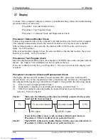
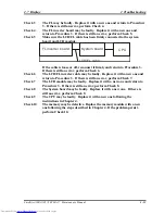
Procedure 5 Connector Check and Replacement Check
The HDD or system board may be faulty. Disassemble the computer following the steps
described in Chapter 4 and perform the following checks:
Check 1
Make sure the following connectors have been firmly connected to the
HDD, system board and CPU.
HDD
System board
CPU
If any connector is loose or off, reconnect it firmly and return to Procedure 1.
If there is still an error, perform Check 2.
Check 2
The HDD may be damaged. Replace it with a new one following the
disassembling instructions in Chapter 4. If the problem persists, perform
Check 3.
Check 3
The System board may be damaged. Replace it with a new one following
the disassembling instructions in Chapter 4. If the problem persists,
perform Check 4.
Check 4
The CPU may be damaged. Replace it with a new one following the
disassembling instructions in Chapter 4.
Содержание Satellite A100 Series
Страница 2: ...ii S No ...
Страница 15: ...Chapter 1 Hardware Overview ...
Страница 16: ...1 Hardware Overview ii Satellite A100 A105 TECRA A7 Maintenance Manual ...
Страница 40: ...2 Troubleshooting 2 i Satellite A100 A105 TECRA A7 Maintenance Manual 2 Chapter 2 Troubleshooting ...
Страница 53: ...2 Troubleshooting 2 4 System Board 2 10 Satellite A100 A105 TECRA A7 Maintenance Manual ...
Страница 73: ...Chapter 3 Diagnostic Programs ...
Страница 76: ......
Страница 115: ...3 5 System Test 3 Diagnostic Programs Satellite A100 A105 TECRA A7 Maintenance Manual 39 ...
Страница 146: ...Chapter 4 Replacement Procedures 4 1 ...
Страница 147: ...4 Replacement Procedures 4 ii Satellite A100 A105 TECRA A7 Maintenance Manual ...
Страница 154: ...4 Replacement Procedures 4 1 General 4 2 Satellite A100 A105 TECRA A7 Maintenance Manual ...
Страница 222: ...6000 1 Appendices ...
Страница 223: ...Appendices App ii Satellite A100 A105 TECRA A7 Maintenance Manual ...
Страница 236: ...Appendices Apx B Board Layout B 2 Satellite A100 A105 TECRA A7 Maintenance Manual Figure B 2 Board layout back ...


