21-EN
22-EN
– 11 –
■
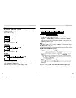
Wiring connection
(single system)
REQUIREMENT
•
Be sure to connect the wires matching the terminal
numbers.
Incorrect connection causes a trouble.
•
Keep a margin (approx. 100 mm) on a wire to hang
down the electrical control box at servicing, etc.
•
The low-voltage circuit is provided for the wired
remote controller.
(Do not connect the high-voltage circuit)
▼
When using the supplied wireless remote
controller
The system interconnection wire can be connected
without removing the front panel.
1
Remove the air intake grille.
Open the air intake grille upward and pull it toward
you.
2
Remove the terminal cover.
3
Insert the system interconnection wire
(according to the local rule) into the pipe
hole on the wall.
4
Take the system interconnection wire out
of the cable slot on the rear panel so that it
protrudes about 150 mm from the front.
5
Insert the system interconnection wire fully
into the terminal block and secure it tightly
with screws.
Tightening torque: 1.2 N·m (0.12 kgf·m)
Secure the earth wire with the earth screw.
6
Clamp the system interconnection wire
with the cord clamp.
7
Attach the terminal cover and the air intake
grille to the indoor unit.
CAUTION
•
Be sure to refer to the wiring diagram attached
inside the front panel.
•
Check local electrical cords and also any speci
fi
c
wiring instructions and limitations.
Screw
Terminal block for
Indoor / Outdoor
connecting
Earth screw
Screw
Cord clamp
Terminal
cover
Unit : mm
Earth wire
Connecting
cable
System
interconnection
wire
about
150 mm
70 mm
10 mm
10 mm
40 mm
<Stripping length of the system interconnection wire>
Cord clamp
Earth screw
System
interconnection
wiring
<Single system connection>
■
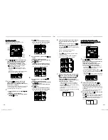
Wiring connection (twin,
triple, double twin system)
1
Connect a header unit by following the
procedure of wiring connection for single
system.
Unit: mm
Earth wire
Connecting
cable
10 mm
40 mm
<Stripping length of the system interconnection wire>
2
Connect system interconnection wire 1
and 2 of follower unit to terminal 1 and 2 on
terminal block respectively.
System interconnection wire 3 is not used.
3
Connect the earth wire to the earth screw
located on the underside of the electrical
control box.
4
Clamp the system interconnection wire
with the cord clamp.
5
Attach the terminal cover and the air intake
grille to the indoor unit.
Cord clamp
Earth screw
System
interconnection
wiring
Cord clamp
Screw
Screw
Earth line
Wiring cove
Terminal
block
Power supply
wire of
fl
ow
selector unit
<Twin, triple, double twin system connection>
▼
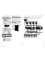
When using optional wired remote controller
The system interconnection wire and the wired remote
controller wire can be connected without removing the
front panel.
1
Remove the air intake grille.
Open the air intake grille upward and pull it toward
you.
2
Remove the terminal cover and the clamp
base.
3
Insert the system interconnection wire and
wired remote controller wire (according to
the local rule) into the pipe hole on the wall.
4
Take the system interconnection wire
and wired remote controller wire out of
the cable slot on the rear panel so that it
protrudes about 150 mm from the front.
5
Insert the wired remote controller wire
fully into the central control / wired remote
control terminal block,
3
,
4
, , , and
secure it tightly with screws.
•
Strip off approx. 9 mm the wire to be connected.
•
Non polarity, 2 core wire is used for wiring of
the wired remote controller. (0.5 mm
2
to 2.0
mm
2
wires)
6
Clamp the wired remote controller wire with
the cord clamp.
7
Install the clamp base with a screw.
8
Insert the system interconnection wire fully
into the terminal block and secure it tightly
with screws.
Tightening torque: 1.2 N·m (0.12 kgf·m)
Secure the earth wire with the earth screw.
9
Clamp the system interconnection wire
with the cord clamp.
10
Attach the terminal cover and the air intake
grille to the indoor unit.
CAUTION
•
Be sure to refer to the wiring diagram attached
inside the front panel.
•
Check local electrical cords and also any speci
fi
c
wiring instructions and limitations.
•
Do not catch the wired remote controller wire when
installing the clamp base.
1111056499_(01)_EN.indb 11
1111056499_(01)_EN.indb 11
10/13/14 9:13 AM
10/13/14 9:13 AM

