Air to Air Heat Exchanger with DX Coil Unit
Installation Manual
Air to Air Heat Exchanger with DX Coil Unit
Installation Manual
– 5 –
3
Restrictions on system construction
System combinations available
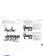
The Air to Air Heat Exchanger with DX Coil Unit can be connected to a Super Module Multi system -i.
Range of combination
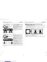
1. The Air to Air Heat Exchanger with DX Coil Unit can be connected with either one of the following multi systems:
• System with Air to Air Heat Exchanger with DX Coil Unit and air conditioner indoor units
• Air to Air Heat Exchanger with DX Coil Unit system
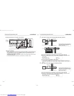
2. The overall capacity (HP) of air conditioner indoor units and Air to Air Heat Exchanger with DX Coil Unit should
be 80 to 135 % of that of outdoor units.
3. When calculating the connection capacity of the indoor unit, use the following horse power:
System with Air to Air Heat Exchanger with DX Coil Unit and air conditioner indoor units
Air to Air Heat Exchanger with DX Coil Unit system
The Air to Air Heat Exchanger with DX Coil Unit and the concealed duct type fresh air intake unit cannot be used
together in the same system.
Model name
MMD-
VNK502HEXE-TR
VN502HEXE-TR
VNK802HEXE-TR
VN802HEXE-TR
VNK1002HEXE-TR
VN1002HEXE-TR
HP
1.0
1.7
2.0
Air conditioner indoor units
Air to Air Heat Exchanger
with DX Coil Unit
Air to Air Heat Exchanger with DX Coil Unit
4
Selection of installation place
CAUTION
•
Do not install the Air to Air Heat Exchanger with
DX Coil Unit in a location subject to a risk of
exposure to a combustible gas.
If a combustible gas leaks and stays around the unit,
a fire may occur.
•
Install the unit so that the air discharge is located
at least 1.5 m from the nearest fire alarm.
Otherwise, when a fire occurs, the fire alarm may be
late to detect it, or may not detect it at all.
Install the indoor unit in a place where cool / warm
air circulates evenly.
Avoid installing in the following places.
• Places where the outside temperature falls below
5 °C. (If the temperature around the unit falls below
5 °C, water in humidifier freezes and the water will
leak.) (VNK type only)
• Places where air pipes are installed in the ceiling
cavity.
• Place exposed to air with high salt content (seaside
area)
• Place exposed to large quantities of sulfide gas (hot
spring).
(Should the unit be used in these places, special
protective measures are needed.)
• A restaurant kitchen where a lot of oil is used or place
near machines in a factory (Oil adhering to the heat
exchanger and resin part (turbo fan) in the indoor
unit may reduce the performance, generate mist or
dew drop, or deform or damage resin parts.)
• Places where obstacles disturbing the air current
such as a ventilation hole or lighting apparatus are
near the unit. (The performance of the unit may be
deteriorated or the unit may not work due to
disturbance of the air current.)
• Do not use the air conditioner for special purposes
such as preserving food, precision instruments, or
art objects, or where breeding animals or growing
plants are kept. (This may degrade the quality of
preserved materials.)
• Place where any of high-frequency appliances
(including inverter devices, private power
generators, medical equipment, and communication
equipment) and inverter-type fluorescent light is
installed.
(A malfunction of the air conditioner, abnormal
control, or problems due to noise to such appliances
/ equipment may occur.)
• Places where there is something that must not
become wet. When the humidity reaches 80 % or
more, or when the draining pipe is clogged, water
droplets may fall from the unit.
• Place near a door or window exposed to humid
outside air (Dew dropping may form.).
• Place where special spray is used frequently.
• Places such as outdoors or under the eaves (where
rain may fall directly on the unit).
• Do not use the unit in chemical plants with a cooling
system which uses liquid carbon dioxide, etc.
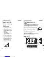
Installation space
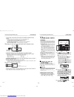
Leave ample space for installation or servicing.
REQUIREMENT
• Before installing indoor units, attach any accessories
(drain-up kit, etc.: separately purchased) to them. In
addition, make inspection opening on both sides of
each unit.
• The size of inspection opening should be 600 mm ×
600 mm.
200 mm or
more
1000 mm or
more
200 mm
600 mm
Inspection opening
600 mm
¯
600 mm
9-EN
10-EN
+00ET99805001-2.book Page 5 Tuesday, July 26, 2011 1:39 PM


