– 17 –
Air to Air Heat Exchanger with DX Coil Unit
Installation Manual
Air to Air Heat Exchanger with DX Coil Unit
Installation Manual
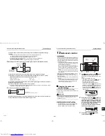
2) When switching between low / high from an external device
SW2 [Low: ON, High: OFF]
• For NRC-01HE (remote controller for the Air to Air Heat Exchanger with DX Coil Unit), the message on the
display is changed. However, when the air conditioner operates Air to Air Heat Exchanger with DX Coil
Unit system linked with air conditioners, ventilation fan speed (Low / High) is changed though the
ventilation amount is not shown on the display.
• If a command is sent to one of the units in the group, all the Air to Air Heat Exchanger with DX Coil Units
in the group operate together.
• The latter operation of the remote controller or the external device overrides the former.
(locally procured)
Adapter for remote ON/OFF control
NRB-1HE
CN705
Control circuit board of the
Air to Air Heat Exchanger
with DX Coil Unit
SW1
Low is applied when SW2
is closed, and High when
it is open.
As these terminals are not used, insulate them.
(1), (3)
No voltage
a-contact
Yellow (2)
Red (3)
White (4)
Green (1)
Black (5)
2 m
3
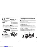
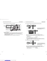
Connecting an auxiliary fan or monitoring operation output (External Output)
Connect to the terminal block for external output (1 and 2) in the electrical control box
Connection wire (locally procured): 2-core wire (H07 RN-F or 60245 IEC 66) 1.0 mm
2
to 2.5 mm
2
Contact is on during normal operation as factory default.
• Contact is off during nighttime heat purge operation or while fan operation is off to protect the unit.
• The operation output settings can be changed. Refer to “Setting for changing the operation output” on
page 21.
4
Connecting an electric damper (electric shutter) (External Output)
Connect to the terminal block for external output (3 and 4) in the electrical control box
Connection wire (locally procured): 2-core wire (H07 RN-F or 60245 IEC 66) 1.0 mm
2
to 2.5 mm
2
Rated contact
Maximum: 240 VAC, 1 A
Minimum: 220 VAC, 100 mA
24 VDC, 1 A
5 VDC, 100 mA
Rated contact (3 to 5: Total value with abnormal signal output)
Maximum: 240 VAC, 1 A
Minimum: 220 VAC, 100 mA
24 VDC, 1 A
5 VDC, 100 mA
Power supply
Contact
Auxiliary
fan
Terminal block for external output
Lamp or management device
Terminal block for external output
If external devices is used working at a higher
voltage and current than the rated values, install
a relay according to the diagram below.
Rated relay: 220-240 VAC
To power supply
Relay contact
External device
Contact
External device
External device
220-240 V~, 50 Hz
Power supply
Contact
Electric
damper
Terminal block for external output
If external output is used working at a higher
voltage and current than the rated values, install
a relay according to the diagram above (diagram
for connecting an auxiliary fan).
Rated relay: 220-240 VAC
220-240 V~, 50 Hz
33-EN
34-EN
+00ET99805001-2.book Page 17 Tuesday, July 26, 2011 1:39 PM

