Air to Air Heat Exchanger with DX Coil Unit
Installation Manual
Air to Air Heat Exchanger with DX Coil Unit
Installation Manual
– 18 –
EN
The electric damper (electric shutter) works during normal operation, and nighttime heat purge
operation.
• The electric damper (electric shutter) also works in the following circumstances:
* While the operation is paused during nighttime heat purge operation
* While operating in cold mode (Temperature is below
−
10 °C.)
• The electric damper (electric shutter) does not work in the following circumstances:
* While the operation is stopped
* Before the monitoring operation of nighttime heat purge operation starts
5
Monitoring an abnormal signal or the operation signal of bypass mode (External Output)
Connect to the terminal block for external output (3 and 5) in the electrical control box
Connection wire (locally procured): 2-core wire (H07 RN-F or 60245 IEC 66) 1.0 mm
2
to 2.5 mm
2
It is possible to monitor an abnormal signal or the operation signal of bypass mode from the Air to Air
Heat Exchanger with DX Coil Unit.
Detection of an abnormal signal is possible, as factory default.
• To change settings so that the operation signal of bypass mode can be detected, refer to “Abnormal signal
/ bypass mode signal output setting” on page 22.
6
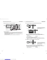
Connecting a humidistat, etc. (VNK type only)
Remove the short wires fixed on the terminal block TB4 with screws. (You need not use these wires.)
Connect a humidistat, etc. to the terminal block using the screws.
Rated contact (3 and 4: Total value with output of the electric damper)
Maximum: 240 VAC, 1 A
Minimum: 220 VAC, 100 mA
24 VDC, 1 A
5 VDC, 100 mA
Power supply
Contact
Terminal block for external output
Abnormal signal or
operation signal of
normal ventilation
220-240 V~, 50 Hz
Contact rating:
1 A or more
Humidistat, etc.
(Closed when humidification is allowed.)
AC220-240 V
13
Advanced control
REQUIREMENT
When using the Air to Air Heat Exchanger with DX Coil
Unit for the first time, it will take some moments after the
power has been turned on before the remote controller
becomes available for operations: This is normal and is
not indicative of trouble.
• Concerning the automatic addresses (The automatic
addresses are set up by performing operations on the
outdoor interface circuit board.)
While the automatic addresses are being set up, no
remote controller operations can be performed. Setup
takes up to 10 minutes (usually about 5 minutes).
• When the power is turned on after automatic address
setup
It takes up to 10 minutes (usually about 3 minutes) for
the outdoor unit to start operating after the power has
been turned on.
Before the Air to Air Heat Exchanger with DX Coil Unit
was shipped from the factory, all units are set to
[STANDARD] (factory setting). If necessary, change the
indoor unit settings.
The settings are changed by operating the wired remote
controller.
* The settings cannot be changed using only a wireless
remote controller, simple remote controller or group
control remote controller by itself so install a wired
remote controller separately as well.
Changing the advanced
control settings
Basic procedure for changing the settings
Change settings while the power is turned off. (Be sure
to stop operation.)
CAUTION
Do not change any setting codes other than those in this
manual; otherwise, the unit may not work or some
problems may occur.
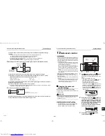
Changing the settings of the Air to Air Heat
Exchanger with DX Coil Unit (For NRC-01HE)
* For RBC-AMT32E, you can change settings using
the same procedure as NRC-01HE. (Display
position is different from that of NRC-01HE.)
1
Push
button and temp. setup
button
simultaneously for at least 4 seconds.
After a while, the display flashes as shown in the
figure.
Confirm that the CODE No. is [01].
• If the CODE No. is not [01], push
button to
erase the display content, and repeat the
procedure from the beginning.
(No operation of the remote controller is
accepted for a while after
button is pushed.)
(While Air to Air Heat Exchanger with DX Coil
Unit are operated under the group control, “ALL”
is displayed first. When
is pushed, the
indoor unit number displayed following “ALL” is
the header unit.)
2
Every time you press the
button, the
unit numbers of the indoor units or the Air to
Air Heat Exchanger with DX Coil Units in the
group are displayed successively. Select the
Air to Air Heat Exchanger with DX Coil Unit
to change settings. When the unit is
selected, the fan starts running to indicate
which unit you have selected.
3
Using TEMP. setup
/
buttons,
specify CODE No. [
].
6
3
1
2
5
4
(* Display content varies with
the indoor unit model.)
35-EN
36-EN
+00ET99805001-2.book Page 18 Tuesday, July 26, 2011 1:39 PM

