– 20 –
Air to Air Heat Exchanger with DX Coil Unit
Installation Manual
EN
Air to Air Heat Exchanger with DX Coil Unit
Installation Manual
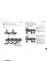
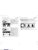
Group control
In a group control, a remote controller can control up to maximum 8 units.
• For wiring procedure and wiring method of the individual line (Identical refrigerant line) system, refer to “Electric
wiring” in this Manual.
• Wiring between indoor units in a group is performed in the following procedure.
Connect the indoor units by connecting the remote controller inter-unit wires from the remote controller terminal
blocks (A/B) of the indoor unit connected with a remote controller to the remote controller terminal blocks (A/B)
of the other indoor unit. (Non-polarity)
• For address setup, refer to the Installation Manual attached to the outdoor unit.
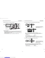
Changing the time before the Filter Sign lights up
The time before the Filter Sign lights up can be changed according to the installation conditions.
* Adjust this setting for the header unit.
• Select [01] in step 3 on page 18.
• Select a value from the table on the below in step 4 on page 19 according to the preferred time before the
Filter Sign lights up.
For better heating performance
When it is hard to become hot due to the location of the indoor unit, room structure, etc., you can raise the detect
temperature for heating. It is recommended that you use a circulator or the like to circulate warm air around the
ceiling.
• Select [06] for CODE NO. in Step 3.
• Select CODE NO. from the following table in Step 4:
* In addition to the above detect temperature shift value, the own detect temperature shift value (Heat: 2.5 °C,
Cool: -2.0 °C) is set for the Air to Air Heat Exchanger with DX Coil Unit in order to intake enough outdoor air. This
setting does not need to be changed, but if you want to change the setting, contact our Customer Support Center.
Code
SET DATA
0000
0001
0002
0003
0004
01
Time before the
Filter Sign lights
up
None
150H
2500H
(Factory
default)
5000H
10000H
Code
SET DATA
0000
0001
0002
0003
0004
0005
0006
06
Detect temperature
Shift value
None
+ 1 °C
+ 2 °C
(default)
+ 3 °C
+ 4 °C
+ 5 °C
+ 6 °C
Setting the single operation of the Air to Air Heat Exchanger with
DX Coil Unit (Setting for the header air conditioner)
Single operation of the Air to Air Heat Exchanger with DX Coil Unit is possible when operation of the Air to Air Heat
Exchanger with DX Coil Unit is linked with that of the air conditioners.
Use the
button of the wired remote controller.
* While the Air to Air Heat Exchanger with DX Coil Unit is in operation,
is displayed on the remote controller.
* Adjust this setting for the header air conditioner in the group when using a system equipped with the Air to Air
Heat Exchanger with DX Coil Unit and air conditioners.
* This setting is invalid when using a system equipped with the Air to Air Heat Exchanger with DX Coil Unit(s) only.
• Select [31] in step 3 on page 18.
• Select [0001] in step 4 on page 19.
REQUIREMENT
Do not change this setting when the operation is linked by a signal from an external device or remotely controlled on
and off (page 16) by using Remote ON/OFF Adapter NRB-1HE (sold separately).
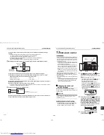
Remote controller sensor
Usually the temperature sensor of the indoor unit senses the temperature. Configure this setting in order to sense
the temperature around the remote controller.
• Select [32] for CODE NO. in Step 3.
• Select CODE NO. from the following table in Step 4:
If the remote controller sensor blinks, an error has occurred on the remote controller sensor.
Set [0000]: Do not use for the remote controller sensor, or replace the remote controller.
Setting of the unbalanced ventilation Fan speed
SA/EA unbalanced operation of the Air to Air Heat Exchanger with DX Coil Unit is possible.
Use the
button of the remote controller.
* Adjust this setting for all the Air to Air Heat Exchanger with DX Coil Units when group operation is applied.
* Though RBC-AMT32E cannot be used, this setting can still be changed. For details, refer to “Ventilation Fan
speed setting” on page 21.
• Select [48] in step 3 on page 19.
• Select [0001: SA (High) > EA (Low) active] or [0002: SA (Low) < EA (High) active] in step 4 on page 19.
Code
SET DATA
0000
0001
31
Single operation of the fan
Invalid
(Factory default)
Valid
Code
SET DATA
0000
0001
32
Remote controller sensor
Do not use
(default)
Use
Code
SET DATA
0000
0001
0002
48
Unbalanced ventilation Fan
speed
Invalid
(Factory default)
SA (High) > EA (Low)
active
SA (Low) < EA (High)
active
VENT
39-EN
40-EN
+00ET99805001-2.book Page 20 Tuesday, July 26, 2011 1:39 PM

