background image

DP120F/DP125F Removal/Replacement

8-44

March 2000 © TOSHIBA TEC

08-02-58

(3)

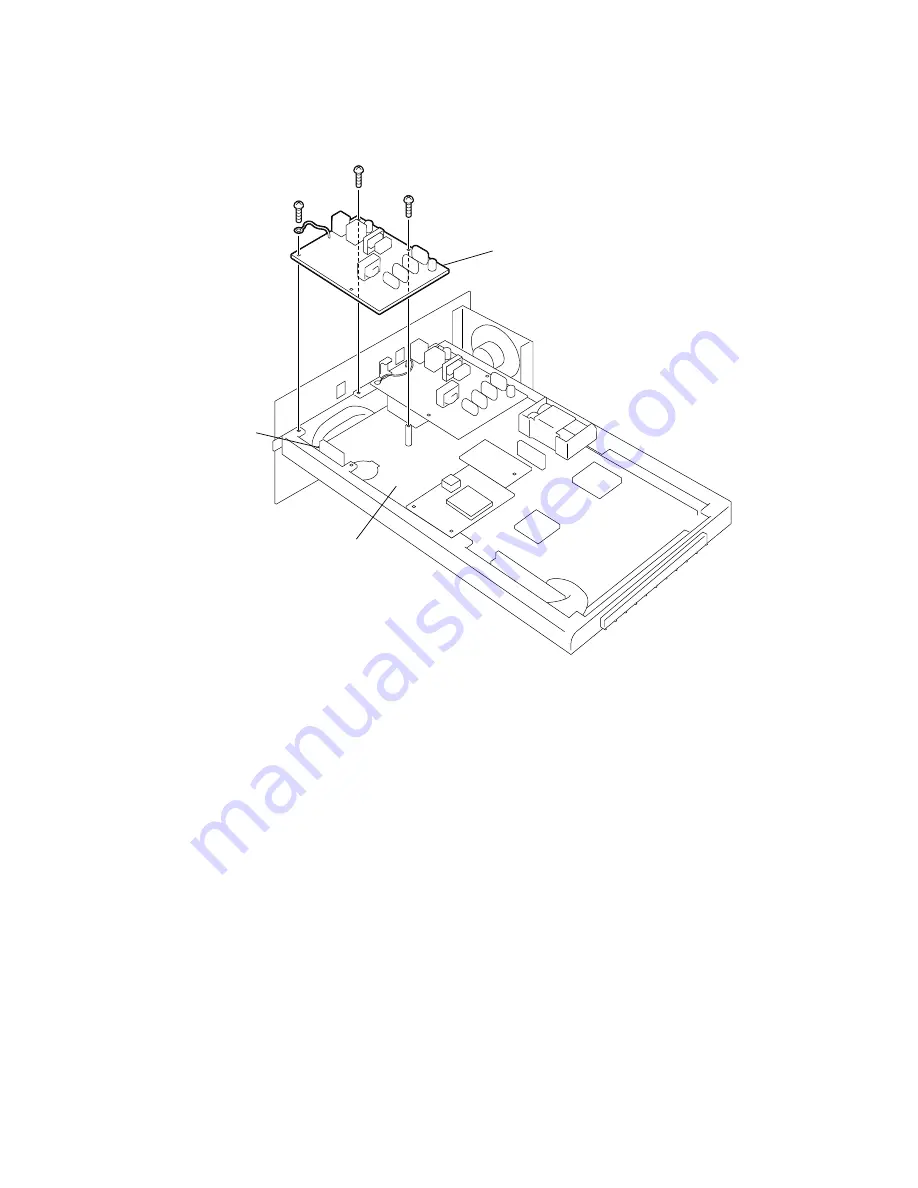
Remove the three screws from the NCU PBA (Line 2). Disconnect the connector on the

NCU PBA (Line 2) from CN4 on the main PBA to remove the NCU PBA (Line 2).

Fig. 8-2-58

(4)

Reassemble the components in the reverse order of disassembly.

 NOTE: Carefully handle the boards that are directly connected together to avoid

damaging the connectors and boards.

NCU PBA (Line 2)

Main PBA

CN4

Содержание DP120F

Страница 1: ...PLAINPAPERFACSIMILE File No 31200001 R0112216901 TTEC ...

Страница 2: ...Chapter 1 Introduction 1 Features 1 1 2 Overview 1 6 2 1 Front View 1 6 2 2 Rear View 1 8 2 3 Operation Panel 1 10 2 4 Function keys 1 13 ...

Страница 3: ...s capa bilities provides maximum office productivity and efficiency Patterns of the multi access are as follows 1 Scan to Memory during Memory Transmission 2 Scan to Memory during Reception 3 Scan to Memory during Substitute Reception 4 Copying during Memory Transmission 5 Reception during Copying 6 Reception during Memory printing 7 Reception during List printing 8 Scan to Memory during Memory pr...

Страница 4: ...s can be registered for each address Some one touch keys also operate as direct function access keys For further details see page 1 13 300 abbreviated dial numbers 300 abbreviated dial numbers can be assigned in the range from No 001 to 999 Alternate number dialing It is possible to assign two facsimile telephone numbers to one abbreviated dial number or one touch dial key one as the primary telep...

Страница 5: ... be set Once set polling receptions are repeated at the same time on the designated day of week Sub address communication The DP120F DP125F supports communication applications using sub address SUB SEP PWD commands conforming to ITU T Sub address communication is possible by keypad dialing one touch key dialing and abbreviated dialing using the sub address settings in Comm Op tions Security commun...

Страница 6: ... cover sheet also allows image data such as a company logo to be included Account code By entering a different account code for each destination at the time of transmission account codes will identify when for whom and to whom a particular fax message was sent Department code Permits assigning 99 department codes to control access and track activity These codes are setup beforehand and must be use...

Страница 7: ... order with page one on top This feature is automatically deactivated when residual memory becomes low DP120F DP125F customers receiving large or busy documents should install an optional memory PBA before using this feature Recovery transmission Documents that have gone through the redial count limit will not be cleared but stored for a programmed period of time Such documents can be recovered to...

Страница 8: ...er printing Operation panel Used to perform programming and operation of the facsimile machine Paper tray Holds up to 550 sheets of recording paper Right side cover Provides access to the recording paper feed path Fig 1 2 1 01 02 01 Document exit tray Document exit tray extension Recording paper exit tray Operation panel Paper tray Top cover release lever Document tray Document guides Right side c...

Страница 9: ...e This interface is used for connection to personal computers for Scanning Printing and pro gramming various settings from a PC Document tray Place documents face down on this tray to transmit or copy Scanner cover release button Provides access to the document scanner area for periodic cleaning or clearing jammed origi nals Document guides Adjust the guides to the edges of the document to help en...

Страница 10: ...nal telephone connector Connection for an External Telephone set Handset connector Connection for the optional Handset unit Line 2 connector Connection for the 2nd telephone line cord from wall or PSTN system DP125F Standard DP120F Option AC inlet Fig 1 2 2 01 02 02 Handset Connector Line 1 Connector Line 2 Connector AC Inlet ExternalTelephone Connector ...

Страница 11: ... 02 05 Fig 1 2 4 01 02 06 Upper recording paper tray Middle recording paper tray optional Lower recording paper tray optional Upper recording paper tray Lower recording paper tray optional Handset optional for US CA model only Bypass tray DP125F standard DP120F optional Bypass tray DP125F standard DP120F optional Handset optional for US CA model only ...

Страница 12: ...NG PAPER Lamp Blinks when the recording paper supply has been depleted TONER Lamp Blinks when the toner is nearly or entirely exhausted DRUM Lamp Blinks when the Process Unit is at or near its end of life ALARM Lamp Is blinks when any error other than those listed above occurs 2 LINE 1 Lamp Blinks when communicating using Line 1 3 LINE 2 Lamp Blinks when communicating using Line 2 4 PC COMM Lamp B...

Страница 13: ...R ENTRY mode 8 DELETE Key This key is used to delete characters in CHARACTER ENTRY mode 9 Dial Keypad Use these 12 keys just like a telephone keypad to dial telephone facsimile numbers 10 MULTI Key Performs Multi address Transmissions Broadcast or a Multi polling receptions 11 SPEED DIAL Key Used for accessing Abbreviated Alphabet or Group dialing telephone directories 12 REDIAL PAUSE Key Press th...

Страница 14: ...d mode is se lected none of the MODE lamps will be illuminated 19 Menu Keys Keys These keys are used to scroll and highlight desired LCD menu prompts The is also used as the TONE Key The key is helpful to access various services requiring touch tone dialing when you are connected to a Rotary line 20 ENTER Key Press this key to enter a selected menu item or select a menu entry 21 JOB CANCEL Key Use...

Страница 15: ...amming DELAYED COMM Schedules a delayed communication job to be performed at a designated time DIRECT TX Allows transmission direct from the document feeder without the use of memory LOW SPEED TX Used to select a lower transmission speed to transmit a document when poor line conditions are expected such as when transmitting to an overseas location that can only accept low speed data ITU MAILBOX Us...

Страница 16: ...set the functions related to the PCL Board when the optional GA 1020 PCL Print Kit is installed JOURNAL Used to print a communication journal PREV TX RPT Displays or prints the result of previous transmission jobs RESERVATION LIST Prints a Job Reservation List SECURE RX Enables or disables Secure RX CHECK E MAIL Used to receive an E mail immediately Requires optional GD 1040 Internet FAX Kit and G...

Страница 17: ...Transceiver 2 4 4 Telephone Functions 2 5 5 Liquid Crystal Diode LCD Display 2 5 6 Special Communication 2 6 7 Others 2 6 8 Operating Environmental Conditions 2 6 9 Maintenance 2 7 10 Power Source Size Weight 2 8 11 Applicable Standard 2 8 12 Software Performance Table 2 9 ...

Страница 18: ...osition detected by a photo interrupter Document leading edge 2 mm 2 mm Document trailing edge 0 mm 2 5 mm Fig 2 1 a Max 4mm Remarks The effective scanning width has a mechanical error range of 1 5 For calculating into a pels value multiply each value by 8 i e 8 pels per mm Effective scanning range b Unit mm a 1 line width b White mask L c Effective scanning width d White mask R Paper size a b c d...

Страница 19: ...h When not assisted by an operator With the document exit tray extension stretched out 216 mm width x 420 mm length 8 5 width x 16 5 length Minimum document size 148 mm width x 100 mm length 5 8 width x 3 9 length For documents of width less than 148 mm use a carrier sheet Document thickness Single sheet document 0 05 to 0 15 mm 45 to 120 g m2 For documents of thickness less than 0 06 mm use a car...

Страница 20: ... to 28 lbs xerographic bond Recording paper tray capacity 550 sheets cassette 20 lb paper Bypass tray capacity 100 sheets cassette 20 lb paper Recommended paper Letter Legal Hammer Mill TIDAL DP 20 lb A4 TOSHIBA Copier Paper European paper Recording paper stack Exit Left side Capacity Letter A4 300 sheets 20 lb paper Legal 100 sheets 20 lb paper Effective recording range Fig 2 2 Paper size Size Ho...

Страница 21: ...t 14 4 Kbps Reception level V 17 43 dBm to 3 dBm V 34 43 dBm to 9 dBm Transmission level 15 dBm to 0 dBm 1dB incremental settings are available 3 Transceiver Line used Telephone line Communication mode Exclusive mode CRP connection G3 mode ECM Communication mode specifications Horizontal scanning density Vertical scanning density Data compression system Transmission speed image signal Modulation s...

Страница 22: ...iated dialing one touch dialing alphabet dialing direct dialing or group dialing Group dialing 50 groups abbreviated dialing one touch dialing alphabet dialing and direct dialing Alternate number dial function Available Maximum number of dialing digits 1600 digits JOB ENTRY FULL will be displayed when this limit is reached 5 Liquid Crystal Diode LCD Display Number of characters displayed Dot matri...

Страница 23: ...r history Test mode RDC Remote Diagnosis Configuration Function setting Print reduction Journal transmission reception report Paper size change 8 Operating Environmental Conditions Operating Temperature 10 to 29 C 50 to 84 F Humidity 20 to 80 RH with no condensation Storing Transporting Facsimile Unit Temperature 0 to 35 C 32 to 95 F 12 months Humidity 20 to 85 RH 12 months with no condensation Dr...

Страница 24: ...he ITU T 1 Test Chart Slerexe Letter Yields will vary with other image densities Name Timing to replace Drum unit 10 000 sheets Letter A4 Developer assembly 60 000 sheets Toner cartridge Initial cartridge 750sheets Supply cartridge and thereafter 3 100 sheets Fuser cleaner with each toner cartridge Ozone filter with each drum unit Fan motor 30 000 hours Fuser unit 60 000 sheets Transfer charger un...

Страница 25: ... top transceiver External dimensions 590 mm W x 596 mm D x 338 mm H 23 2 W x 23 5 D x 13 3 H excluding protrusions and optional parts When the optional recording paper trays is installed 545 mm H 21 5 H Weight Unit About 24 5 kg 38 6 lb 11 Applicable Standard Post Telephone Telagram PTT FCC Part 68 US model DOC CA model CRT21 EU model Safety standards UL CUL 1950 US CA model EN60950 EU model CB Ra...

Страница 26: ...s per 1 box Maximum 128 digits Maximum 128 digits Maximum TBD digits 2912Kbyte a Normal 7008Kbyte b with Op Mem 4MB 3072Kbyte c 160Kbyte a 7168Kbyte d 160Kbyte b 160Kbyte using only memory RX 7008Kbyte a Normal 7168Kbyte b 160Kbyte a 160Kbyte using only memory RX 8192Kbyte 100 jobs Maximum 99 pages Maximum Sub Item Keypad dial Abbreviated dial Alphabet dial One touch dial Multi address group Multi...

Страница 27: ...Paper Storage 3 3 3 Unpacking 3 4 4 Accessories 3 7 4 1 List of Accessories 3 7 4 2 Installing the Accessories 3 8 5 Hardware Options 3 19 5 1 Remarks before Starting Work 3 19 5 2 Attaching Hardware Options 3 21 6 Connecting to the Power and Telephone Lines 3 34 7 Memory Clear 3 35 8 Country Region Setting Operation 3 36 9 Remarks on Moving the Machine 3 38 01 12 ...

Страница 28: ...ching the accessories Attaching the hardware options Connect the machine to power and telephone line Memory Clear Country Region setting operation Start Preparation Refer to page 3 2 Refer to page 3 4 Refer to pages 3 7 Refer to page 3 8 to 3 18 Refer to pages 3 19 to 3 33 Refer to page 3 34 Refer to page 3 35 Refer to pages 3 36 to 3 37 Refer to page 4 1 Function setting End 01 12 ...

Страница 29: ...reas where sudden temperature changes may occur such as near a refrigerator etc Water splashes or chemical contamination Areas where dust iron powder poison gases etc may arise Areas subject to heavy vibration Areas where products with strong magnetic parts are around Near radios TV sets other electric appliances etc Provide space as shown in Figure 3 2 1 for placing the facsimile unit considering...

Страница 30: ...tore it in the packing paper Do not store paper stacks standing on end or leaning against something Keep it flat The following factors may result in poor performance of the paper or may result in poor image quality Using paper other than that recommended Pieces of recording paper sticking together Printing on the back side of a sheet that has already been used or two sided printing Paper which has...

Страница 31: ...tc that is stable and strong 2 Cut the bands around the outer carton and lift the outer carton off of the machine NOTE When taking the machine out of the carton lift the unit in the manner shown above Retain the carton plastic bags cushions etc because they will be needed later for moving or transporting the machine 3 Carefully remove the packing materials from the unit and accessories 4 Check the...

Страница 32: ...arton Fig 3 3 2 3 3 02 Packing pad Recording paper tray Box Facsimile unit Outer carton Packing pad Packing pad Packing pad Box Packing mate rial Box Packing material Drum unit Developer assembly Packing material Packing material Phone line cord Power cord Packing material Operator s manual Fuser cleaner Packing material Tape ...

Страница 33: ...DP120F DP125F Installation 3 6 March 2000 TOSHIBA TEC Paper tray Bypass tray Fig 3 3 4 3 3 04 Fig 3 3 3 3 3 03 Packing pad Packing pad Outer carton Paper tray Outer carton Packing material Bypass tray ...

Страница 34: ...ies are shipped with the machine Fig 3 4 1 Facsimile unit 1 Phone line cord 1 Document exit tray 1 Operator s manual 1 Power cord 1 Developer assembly 1 Drum unit 1 Recording paper tray 1 Charger cleaner kit 1 Fuser cleaner 1 Warranty card 1 Overlay 1 US model only Toshiba Viewer Bypass tray 1 CD ROM 1 DP125F only ...

Страница 35: ...ty do not touch the green drum or expose it to room light for more than the 3 minutes Never expose the drum to direct sunlight 1 Grasp the Top cover release lever to open the Top cover 2 Hold the Developer assembly with both hands and shake the cartridge back and forth several times Developer assembly Fig 3 4 2 3 4 02 Top cover Top cover release lever Fig 3 4 3 3 4 03 ...

Страница 36: ...y remove it from the cartridge 4 Position the Drum unit with the green drum surface facing the toner roller on the Devel oper assembly Without touching the green drum surface hook the drum unit to the De veloper assembly The following figure shows how to join the Drum unit and the Devel oper assembly Protective strip Developer assembly Drum unit Developer assembly Fig 3 4 4 3 4 04 Fig 3 4 5 3 4 05...

Страница 37: ...he three shafts on the de veloper drum assembly sides with the slots in the machine frame Lower the unit into the machine The following figure shows how the shafts on the developer drum assembly align with the slots Fig 3 4 6 3 4 06 Fig 3 4 7 3 4 07 Developer assembly with drum unit attached Green handle Green handle ...

Страница 38: ...quares on the Drum unit until the Drum unit clicks into place The following figure shows how to press the Drum unit into place 7 Close the top cover Grasp the Top cover release lever firmly close the Top cover and release the lever Drum unit Top cover Fig 3 4 8 3 4 08 Fig 3 4 9 3 4 09 ...

Страница 39: ...ure the Power switch is turned OFF 2 Plug in the Power cord into the machine 3 Connect the phone line cord to the LINE connector on the machine and wall jack 4 Plug the Power cord into the AC wall outlet Power switch Power cord Phone line cord LINE1 PHONE HANDSET Fig 3 4 10 3 4 10 Fig 3 4 11 3 4 11 ...

Страница 40: ...ne CAUTION Do not place heavy objects on the Recording paper exit tray 2 Insert the tabs of the Document exit tray into the slots on the left side of the machine Extend the Document exit tray extension for large documents CAUTION Do not place heavy objects on the Document exit tray Fig 3 4 12 3 4 12 Fig 3 4 13 3 4 13 Recording paper exit tray Hook Document exit tray exten sion Tab Document exit tr...

Страница 41: ...er 2 Specifications for recording paper specifications 1 Pull the Paper tray out 2 Insert the Paper size indicator sheet into the slot of the Paper tray with the appropriate paper size showing through the window Paper tray Paper size indicator sheet Window Fig 3 4 14 3 4 14 Fig 3 4 15 3 4 15 ...

Страница 42: ...C 3 15 DP120F DP125F Installation 3 Do not fan the paper Make sure that the corners of paper are neatly aligned 4 Press the Paper pressure plate down until it clicks Paper pressure plate Fig 3 4 16 3 4 16 Fig 3 4 17 3 4 17 ...

Страница 43: ...BA TEC 5 Insert up to 550 sheets into the Paper tray CAUTION To avoid paper jams do not exceed the Upper limit line on the paper guide 6 Push the Paper tray all the way into the machine Upper limit line Paper tray Fig 3 4 18 3 4 18 Fig 3 4 19 3 4 19 ...

Страница 44: ...P125F Installation 4 2 5 Fuser Cleaner 1 Grasp the Top cover release lever to open the Top cover 2 Remove the new Fuser cleaner from its plastic bag and install it Fig 3 4 20 3 4 20 Fig 3 4 21 3 4 21 Top cover release lever Fuser cleaner ...

Страница 45: ...DP120F DP125F Installation 3 18 March 2000 TOSHIBA TEC 3 Close the Top cover Grasp the Top cover release lever firmly close the Top cover and release the lever Fig 3 4 22 3 4 22 ...

Страница 46: ...F Wait several minutes until the thermal fuser unit cools down CAUTION Always work on a suitable table or bench The working area must be well ventilated Always be sure to use the correct screws and fasteners If an in correct screw or fastener is used it may result in binding or cause some other obstruction with a nearby part Also be careful not to lose screws Take care that cables and connectors a...

Страница 47: ...e very careful when handling the LSU Hold it with two hands do not touch the glass surface do not drop or handle it roughly do not disassemble etc Be sure to remove attachments and accessories as required such as the Developer assembly Document exit tray etc ...

Страница 48: ...d below the tray installed as a standard feature With the standard tray and two optional tray installed the total capacity is 1 650 sheets All trays use the front loading design Composing Parts Paper tray 1 Installing Procedure Before beginning power the unit off and read through 5 1 Remarks Before Starting Works Page 3 19 1 Lift the machine and install it on the alignment pins of the Optional pap...

Страница 49: ... Power switch ON and check the following Sensor test in Function test of test mode Refer to pages 11 20 to 11 21 Load the document and press the COPY key Check if copying and feeding normally take place from both paper trays Adjust the paper tray for different paper size if required NOTE Follow the same procedure to install an additional optional paper supply ...

Страница 50: ...te down until it clicks See page 3 15 5 Install the paper and push the Paper tray all the way into the machine Switching Letter LTR and Legal LGL 1 Remove the Paper tray from the machine and remove the paper 2 Remove the Paper guide Install the Paper guide in the correct position for the new paper size NOTE The paper size positions are indicated on the base of the Paper tray Paper guide Fig 3 5 2 ...

Страница 51: ...l the Paper guide in the correct position for the new paper size NOTE The paper size positions are indicated on the base of the Paper tray 3 Remove the two M 3x6 screws each from the Paper guides A to release the separation claw plates from the Paper pressure plate 5 Remove the paper size indicator sheet and re insert it so that the new paper size shows through the window See page 3 14 6 Press the...

Страница 52: ...ption is for US CA model only Composing Parts Cradle 1 Handset 1 Handset cable 1 Cradle stay 1 Curl cord 1 Installing Procedure Before beginning power the unit off and read through 5 1 Remarks Before Starting Works Page 3 19 1 Slide the Cradle stay into the Cradle until it clicks And connect the Handset cable jack Handset cable Cradle Cradle stay Fig 3 5 5 3 5 05 ...

Страница 53: ...et cable to the HANDSET connector And connect the curl cord to the handset and Cradle jack 4 After installing turn the Power switch ON and check the following Dial type in User function setting of function settings Refer to page 4 6 Guides Cradle Handset Cradle jack Curl cord Handset cable Fig 3 5 6 3 5 06 Fig 3 5 7 3 5 07 ...

Страница 54: ...he recording paper size LT A4 LEGAL in the paper tray The Bypass tray accepts the paper size LT A4 LEGAL and OTHER Composing Parts Bypass tray 1 Installing Procedure Before beginning power the unit off and read through 5 1 Remarks Before Starting Works Page 3 19 1 Remove the two screws holding the Bypass tray cover Bypass tray cover Screw Screw Fig 3 5 8 3 5 08 ...

Страница 55: ...DP120F DP125F Installation 3 28 March 2000 TOSHIBA TEC 2 Install the Bypass tray 3 Select the paper size by the slide knob Bypass tray Guide Fig 3 5 9 3 5 09 Slide knob Fig 3 5 10 3 5 10 ...

Страница 56: ...March 2000 TOSHIBA TEC 3 29 DP120F DP125F Installation 4 Raise the tray lever 5 Pull up the Bypass tray paper support Fig 3 5 11 3 5 11 Tray lever Bypass tray paper support Fig 3 5 12 3 5 12 ...

Страница 57: ...he reverse order 9 After assembling turn the Power switch ON and check the following Switch test in Individual test of test mode Refer to page 11 10 Sensor test in Function test of test mode Refer to page 11 20 Load the document and press the COPY key Check if copying and feeding normally take place from Bypass tray Paper guide Recording paper Fig 3 5 13 3 5 13 Fig 3 5 14 3 5 14 Tray lever ...

Страница 58: ...ommunication through 2 telephone lines is pos sible Composing Parts NCU PBA 1 Modem PBA 1 Bind screw M 3X8 B tight zc 5 Installing Procedure Before beginning power the unit off and read through 5 1 Remarks Before Starting Works Page 3 19 1 Remove the two screws holding the PCB assembly 2 Move the knob in the direction shown by the arrow and pull out the PCB assembly PCB assembly Screw Knob Screw F...

Страница 59: ...1 or W2 according to the country region Refer to page 3 37 for the details for connection 6 Directly connect the Modem PBA connector with the MAIN PBA connector CN8 7 Attach the Modem PBA with the two screws 8 Reinstall the remaining components in the reverse order 9 After assembling turn the Power switch ON and check the following Modem test in Function test of test mode Refer to page 11 19 Fig 3...

Страница 60: ...ks Page 3 19 1 Remove the two screws holding the PCB assembly 2 Move the knob in the direction shown by the arrow and pull out the PCB assembly See Fig 3 5 15 3 Attach the Locking support 4 Directly connect the Memory PBA connector with the MAIN PBA connector CN7 US CA TW model EU AU ASIA HK model Fig 3 5 18 3 5 18US 3 5 18EU 5 Reinstall the remaining components in the reverse order 6 After assemb...

Страница 61: ...g the unit hold the plug but not the cord Be certain to connect the machine to a properly grounded wall outlet Procedure 1 Ensure that the Power switch is OFF 2 Plug the Power cord into the wall outlet Be sure the outlet is rated for 115VAC 60Hz or 220VAC 50Hz 60Hz and that it is properly grounded before plugging the machine in 3 Connect the phone line cord to the LINE jack on the unit 4 Connect t...

Страница 62: ...ar to initialize the machine before entering the function setup procedures After the memory clear go on to whatever proce dures are necessary Procedure 1 Turn the Power switch OFF 2 Hold down the 1 and 3 keys on the Operation panel and turn the Power switch ON 3 Hold the three keys down simultaneously for a count of 3 then release the keys ...

Страница 63: ...e country region setting operation is changed To change the destination therefore the memory clear operation is required This operation will clear all the setting information except the below Drum counter Fuser temperature rank Print edge margin COUNTRY REGION CODE 01 12 1 US CA LA 49 DE 44 GB 39 IT 32 BE 31 NL 358 FI 34 ES 43 AT 41 CH 45 DK 47 NO 351 PT 46 SE 33 FR 61 AU NZ 30 GR 65 SG 852 HK 886...

Страница 64: ...20F DP125F Installation Country Region setting of NCU PBA by FG harness 3 08 01 Fig 3 8 1 FG harness DE GB NL IT AT BE CH SE DK NO FI PT FR ES GR IE ZA SG HK AU NZ W2 W2 W2 W1 W2 W2 W2 W2 W1 W2 W1 W2 W2 W2 W2 W2 W2 W2 W2 W2 W2 01 12 ...

Страница 65: ...terials for the drum kit Put the developer as sembly into a proper plastic bag 4 Remove the accessories or attachments from the machine Refer to page 3 7 5 Secure the Top cover and the operation panel with drafting tapes so that they may not be opened and pack them in a carton NOTE The Drum unit should be kept with this machine or it should be discarded DO NOT use this Drum unit in another machine...

Страница 66: ...gs 4 34 1 5 Report and List Options 4 43 1 6 RDC Remote Diagnosis Configuration Service 4 53 1 7 Automatic Supply Order 4 55 2 Service Settings in Test Mode 4 59 2 1 FUNC 0 39 4 61 2 2 PC FUNC 0 7 4 119 2 3 HOME 0 2 4 128 2 4 UAD 0 19 4 132 2 5 EX TYPE 4 160 2 6 ACC DGT1 2 4 161 2 7 2UAD 0 19 4 163 2 8 2EX TYPE 4 191 2 9 2ACC DGT1 2 4 192 ...

Страница 67: ...ither a menu selection method or by setting the numeric value It is possible to select any function by pressing the MENU key then the and keys then ENTER or the numeric key for that function For the initial value list refer to Chapter 12 APPENDIX Remarks To select a menu item you may use the and keys to highlight the required item followed by pressing the ENTER key as described above or you may di...

Страница 68: ...t a language for the LCD messages 1 Select the desired option using the or keys then press the ENTER key ENGLISH This selection will display messages in English ESPAÑOL This selection will display messages in Spanish FRANÇAIS This selection will display messages in French 2 When the OPERATION COMPLETED message is displayed press the STOP key to return to the Standby Mode screen ...

Страница 69: ...s the ENTER key SET TIME FORMAT 1 24HOURS 2 12HOURS SET DATE TIME MM DD YYYY WWW 05 17 2000 WED 24 HOURS Selected to display the time in the 24 hour system For setting the time you can enter in the following range Hour Value 00 through 23 Minute Value 00 through 59 12 HOURS Selected to display the time in the 12 hour system For setting the time you can enter in the following range Hour Value 00 th...

Страница 70: ...4 digit format YYYY MM DD Displays the date in the Year Month Day 4 digit format MM DD YY Displays the date in the Month Day Year 2 digit format DD MM YY Displays the date in the Day Month Year 2 digit format YY MM DD Displays the date in the Year Month Day 2 digit format 7 Use the or keys to move the highlighted row to the desired option row NUMERIC or NAME then press the ENTER key This selection...

Страница 71: ... the section of Character Entries in the Operator s Manual 2 Select the desired option using the or keys to select ADD or NOT NEEDED then press the ENTER key After about 2 seconds SET TERMINAL ID ID NAME MAX40 ENTER NAME ID NAME MAX40 SET TERMINAL ID TEL NUMBER MAX20 INT CODE 1 ADD 2 NOT NEEDED ADD Selected to attach an International Code Country Region Code When selected the symbol is attached be...

Страница 72: ...screen in Step 3 is displayed for the LINE 2 setting In this case repeat 2 through 3 for the LINE 2 requirements 4 When the OPERATION COMPLETED message is displayed press the STOP key to return to the Standby Mode screen 1 1 4 Dial Type MENU 3 4 This setting is used to determine the dial type of the telephone line to which the facsimile unit is connected 1 Use the or keys to move the cursor to the...

Страница 73: ...GIT MAX10 DELETE ACCESS DIGIT Set a number typically 9 1 if it is necessary to access an outside telephone line When a number max 10 digits is entered press the ENTER key During a Chain Dial opera tion it is not necessary to dial 9 1 on numbers associated with a One Touch or Abbrevi ated Number keys therefore the DELETE ACCESS DIGITs will be ignored when they are programmed into a One touch or Abb...

Страница 74: ...the range from 0 minimum to 7 maximum 2 After the OPERATION COMPLETED message is displayed press the STOP key to return to the Standby Mode screen 1 2 2 Alarm Tone Volume Adjustment MENU 4 1 01 02 Use this setting to adjust volume of the alarm tone 1 Use the or keys to move the cursor to the desired position and press the ENTER key SET RINGER VOLUME VOLUME 0 7 0 1 2 3 4 5 6 7 VOLUME Set a value in...

Страница 75: ...m 0 minimum to 7 maximum 2 After the OPERATION COMPLETED message is displayed press the STOP key to return to the Standby Mode screen 1 2 4 Monitor Volume Adjustment MENU 4 1 01 04 Use this setting to adjust volume of the line monitor 1 Use the or keys to move the cursor to the desired position and press the ENTER key SET MONITOR VOLUME VOLUME 0 7 0 1 2 3 4 5 6 7 VOLUME Set a value in the range fr...

Страница 76: ... turns only the fuser section off during the time period selected 1 Use the or keys to select the desired option SUPER P S or PRINTER P S then press the ENTER key SUPER P S To select the SUPER POWER SAVER mode PRINTER P S To select the PRINTER POWER SAVER mode When SUPER P S is selected The screen below is displayed 1 Use the or keys to select one of the three options AUTOMATIC MANUAL or OFF then ...

Страница 77: ... the Printer Power Saver mode OFF To deactivate the Printer Power Saver mode When ON is selected the screen below is displayed Enter the desired TIME period and press the ENTER key START TIME TIME 01 60 MIN 03 PRINTER POWER SAVER 1 ON 2 OFF PRINTER POWER SAVER TIME PERIOD 00 00 00 00 Enter the time period The time on the left is the Printer Power Saver start time or time that the printer unit will...

Страница 78: ...for the Letter head paper setting this function is not available 1 The following screen appears Use the or key to select the desired option ON or OFF then press the ENTER key ON To select the Fax separator page function OFF Not to select the Fax separator page function 2 The following screen appears Use the or key to select the desired option ON or OFF then press the ENTER key FAX SEPARATOR PAGE 1...

Страница 79: ...g paper tray is installed following screen displayed Use the or key to select the desired option LOWER TRAY or AUTO TRAY then press the ENTER key Remarks When the two optional recording paper tray are installed the same screen is displayed PC SEPARATOR PAGE 1 ON 2 OFF LOWER TRAY To print the Separator page from the Lower recording paper tray AUTO SELECT To print the Separator page from a Paper tra...

Страница 80: ...NO Not to select the Department Code function or to set the Department Code feature OFF if it was previously set to ON 2 Enter a Master Code Department Name then press the ENTER key DEPT NAME Enter a maximum of 20 characters for the Department Name When more than 20 char acters are entered the exceeded characters will be ineffective 3 Enter the Master Code then press the ENTER key MASTER CODE Ente...

Страница 81: ...ineffec tive 6 If the Department Number entered in Step 5 is already used for another Department use the or keys to select the desired option CANCEL MODIFY or RETAIN then press the ENTER key CANCEL To cancel the Department Number MODIFY To modify the Department Name of the Department Number RETAIN To retain the preset data of the Department Number 7 After the OPERATION COMPLETED message is display...

Страница 82: ...or key to select the desired option On or OFF then press the ENTER key ON To select the Account Code function OFF Not to select the Account Code function Remarks The Account Code feature can not be used to restrict access The opera tor is prompted for an account code but it is possible to simply press the START key to initiate machine operations If restricted access is desired then the Department ...

Страница 83: ... screen 1 2 10 Document Length MENU 4 1 07 This setting selects whether or not a DOCUMENT JAM error will result when the received document is longer than the specified length 1 Use the or keys to select the desired option 1m or UNLIMITED then press the ENTER key SET PRINT DENSITY DENSITY 2 TO 2 LIGHTER DARKER 2 1 0 1 2 DOCUMENT LENGTH 1 1m 2 UNLIMITED 1m Allows the received document size of up 1 m...

Страница 84: ...confirm dialing and phone line status When two phone lines are simultaneously used for sending the job initiated last will be moni tored 1 Use the or keys to select the desired option ALWAYS or OFF then press the ENTER key ALWAYS Always to set the Line Monitor function OFF Not to set the Line Monitor function 2 After the OPERATION COMPLETED message is displayed press the STOP key to return to the ...

Страница 85: ...2 After the OPERATION COMPLETED message is displayed press the STOP key to return to the Standby Mode screen 1 2 13 ECM Error Correction Mode MENU 4 1 10 This is to set whether the Error Correction Mode ECM which automatically corrects image data affected by line noise or distortion is to be activated or not 1 Use the or keys to select the desired option ON or OFF then press the ENTER key RECEIVE ...

Страница 86: ...tance on resolution rather than the communication and process time it is effec tive to send documents with fine small characters and graphics with fine lines 2 Then the screen below appears Use the or keys to select the desired contrast level NORMAL DARKER or LIGHTER then press the ENTER key DOCUMENT MODE 1 STANDARD 2 FINE 3 U FINE NORMAL For normal documents DARKER For recording in a darker level...

Страница 87: ...cally collated Requires enough memory for the entire multi page document If there is not enough memory memory overflow the copying procedure will be canceled Collation is slower than non collation because the entire document must be scanned into memory first then printing can occur Collating is the responsibility of the operator Memory requirements are limited to one page at a time 1 Use the or ke...

Страница 88: ...ilable When the specified Paper Tray becomes empty the paper will be supplied from another Paper Tray 1 Use the or keys to select the desired option then press the ENTER key LETTER HEAD PAPER 1 OFF 2 BYPASS 3 UPPER TRAY OFF Not to use the Letter Head Paper function BYPASS To select the Bypass Tray UPPER TRAY To select the Upper Recording paper Tray MIDDLE TRAY To select the Middle Recording paper ...

Страница 89: ...below is displayed Enter a value from 01 to 15 in units of minutes as the redial interval then press the ENTER key Remarks When any value outside the specified range is entered it must be set again When 02 COUNTER is selected the screen below is displayed Enter 00 to 14 as the counter value then press the ENTER key When 0 is entered no redialing will occur Remarks When any value outside the specif...

Страница 90: ...ceive Mode This mode is selected to use this machine only as a facsimile unit When it is selected the Ring Delay count is to be set in the range from 01 to 10 followed by the ENTER key Manual Receive Mode This mode is selected to connect the machine to a line which is used as a voice tele phone In this case the machine is used for both voice communication and fax sending receiving the START key mu...

Страница 91: ...ON ONLY To use Line 2 always for reception only TIMER To use Line 2 for reception only for a timer period designated When TIMER is selected the following screen appears Use the or keys to move the cursor to the desired digit enter a desired value or alternate AM PM position When the desired time period is displayed press the ENTER key LINE 2 MODE 1 TX RX 2 RECEPTION ONLY 3 TIMER RECEPTION ONLY TIM...

Страница 92: ...t occur until the remote machine has been contacted With this feature set to ON the greatest productivity of the unit can be realized OFF No documents are scanned to memory All documents are held until the remote unit picks up the line For a Delayed transmission it will be held until the desired transmit time then the remote machine will be contacted then the transmission will take place Remarks I...

Страница 93: ... OFF then press the ENTER key ON To prevent dialing a wrong number for transmissions OFF Will not prevent dialing a wrong number 2 After the OPERATION COMPLETED message is displayed press the STOP key to return to the Standby Mode screen Remarks If the remote party has failed to set their TTI to match the phone number that the machine is operating on then a SECURITY TX will be blocked This machine...

Страница 94: ... name 1 Use the or keys to select the desired option ON or OFF then press the ENTER key ON To select the Cover Sheet function OFF Not to select the Cover Sheet function 2 Then the following screen appears Use the or keys to select the desired option YES or NO then press the ENTER key YES To scan an image document The screen below appears COVER SHEET 1 ON 2 OFF WITH IMAGE 1 YES 2 NO COVER SHEET LOA...

Страница 95: ... document When ON is selected in Step 2 and the COVER SHEET has been set already with an image scanned the following screen is displayed Use the or keys to select the desired option CANCEL or RETAIN then press the ENTER key CANCEL To cancel the cover sheet image already scanned RETAIN To retain the cover sheet image already scanned and cancel a new cover sheet setting 3 After the OPERATION COMPLET...

Страница 96: ...r keys to select the desired option ON or OFF then press the ENTER key ON When set to ON documents are stored after a failed redial attempt for the time period designated below After that time has expired the stored documents are cleared from memory OFF When set to OFF documents are cleared from memory immediately upon completion of the last redial attempt 2 The screen below is displayed Enter the...

Страница 97: ...started Transmitting station ID Name The ID name preset in your facsimile unit if not preset the telephone number of your facsimile unit Maximum of 40 characters Transmission Serial Number A 3 digit serial number assigned to and counted up on every transmission Page Number Total Number of Pages Each page of the document is printed with a page number followed by the total number of pages in the doc...

Страница 98: ...nt TTI and Outside document TTI Remarks FCC regulations require that all facsimiles identify themselves by name and phone number and provide the date and time of the transmission It is recommended that the dealer program this information for the end user during set up or installation The position selection should also be con firmed as either INSIDE or OUTSIDE 2 After the OPERATION COMPLETED messag...

Страница 99: ... AFTER SCAN To enable Send After Scan function When DIAL AFTER SCAN selected the screen below is displayed Use the or keys to select the desired option then press the ENTER key SEND AFTER SCAN 1 DIAL DURING SCAN 2 DIAL AFTER SCAN 1 3 6 Send After Scan MENU 4 2 06 This feature enables you to determine whether dialing starts while the machine is scanning the documents or after the machine has scanne...

Страница 100: ...days of the week is selectable This section describes the procedure for programming a security code or changing an existing security code 1 Use the or keys to select the desired option then press the ENTER key SECURITY CODE To select a security code for the first time or to change an existing security code Go to next step ACTIVITY MODE To set the activity period for Secure RX function Go to step 4...

Страница 101: ...specified time period OFF To de activate automatic Secure RX during a specified time period When 1 ON selected the screen below is displayed Use the or keys to move the cursor to the desired digit enter a desired value or alternate AM PM position when the desired time period is displayed press ENTER key 5 You can also set Secure RX to ON for an entire 24 hour period e g Saturdays Sun days YES To s...

Страница 102: ...ter the OPERATION COMPLETED message is displayed press the STOP key to return to the Standby Mode screen 1 4 2 Memory Reception MENU 4 3 02 This is to set whether the Memory Reception function to store received document data into memory in case recording paper is not possible due to trouble etc is active or not 1 Use the or keys to select the desired option ON or OFF then press the ENTER key SET M...

Страница 103: ... tiple pages B When the RX reduction function is OFF and the received document is longer than the recording paper size the recording image will be divided into multiple pages 1 Use the or keys to select the desired option ON or OFF then press the ENTER key ON Recording will occur with reduction to 75 of the original size OFF No reduction will be applied 2 After the OPERATION COMPLETED message is d...

Страница 104: ...s longer than the specified value no discarding will occur but the recording image will be divided into multiple pages B When the Discard function is set OFF the image portion in the exceeding area will be recorded in a separate page 1 Use the or keys to select the desired option ON or OFF then press the ENTER key ON Discards the data in the area exceeding length of the recording paper OFF Does no...

Страница 105: ... in reverse order In this way the pages of the document will be in correct order 1 Use the or keys to select the desired option ON or OFF then press the ENTER key REVERSE ORDER PRINT 1 ON 2 OFF ON To set the Reverse Order Print function OFF Not to set the Reverse Order Print function 2 After the OPERATION COMPLETED message is displayed press the STOP key to return to the Standby Mode screen ...

Страница 106: ...eceptions will only be allowed when a match is found 1 Use the or keys to select the desired option ON or OFF then press the ENTER key PRIVILEGED RX 1 ON 2 OFF ON To set the Privileged Reception function OFF Not to set the Privileged Reception function Remarks If the remote party sTTI does not match a phone number that is programmed into this machine s Abbreviated Number or One touch key list then...

Страница 107: ...our own station Page Number The page number of 3 digits 1 Use the or keys to select the desired option ON or OFF then press the ENTER key ON To record RTI OFF Not to record RTI Remarks The RTI is added at the bottom in the effective recording range of the received document image The RTI is added even when a communication error or image error oc curs When the recording image is divided into multipl...

Страница 108: ... Memory Reception mode The Collated Print function can be set together with the Receive Multi Copy function In this case data is printed out from the last page to the first page When the residual memory capacity is not enough this setting will be de activated and the normal reception mode will be regained When there is no more residual memory capacity remaining during a re ception in Memory Recept...

Страница 109: ...nu option allows you to select the manner in which journal reports are to be printed When MANUAL is selected The screen below displays the options for the type of journal to be printed manually 1 Use the or keys to select the desired option TX RX JOURNAL TX JOURNAL RX JOURNAL then press the ENTER key TX RX JOURNAL Prints both Transmission and Reception Journals TX JOURNAL Prints only Transmission ...

Страница 110: ... after 150 Rx and Tx activities 1 Use the or keys to select the desired option ON or OFF then press the ENTER key AUTOMATIC JOURNAL 1 ON 2 OFF ON Prints journals automatically after 150 Tx and Rx activities OFF Does not print journals automatically 2 After the OPERATION COMPLETED message is displayed press the STOP key to return to the Standby Mode screen ...

Страница 111: ... Relay Transmission Relay Station Relay Relay Relay Transmission End Terminal 1 The screen below is displayed to select options for Single Transmission Use the or keys to select the desired option ALWAYS ON ERROR or OFF then press the ENTER key ALWAYS Prints after every transmission ON ERROR Prints only when an error has occurred in transmission OFF Disables print 2 The screen below is displayed t...

Страница 112: ...nsmission OFF Disables print 4 The screen below is displayed to select a document added option Use the or keys to select the desired option ON or OFF then press the ENTER key PRINT 1ST PG IMAGE 1 ON 2 OFF ON Adds add the document data in the Memory Transmission Report OFF Does not add document data in the Memory Transmission Report 5 The screen below is displayed to select options for Memory Trans...

Страница 113: ... The screen below is displayed to select options for Multi polling Report Use the or keys to select the desired option then press the ENTER key ALWAYS Prints after every transmission ON ERROR Prints only when an error has occurred in transmission OFF Disables print 7 The screen below is displayed to select a document added option Use the or keys to select the desired option ON or OFF then press th...

Страница 114: ...WAYS Prints after every Relay Transmission ON ERROR Prints only when an error has occurred in transmission OFF Disables print 10 The screen below is displayed to select a document added option Use the or keys to select the desired option ON or OFF then press the ENTER key ON Adds the document data in the Report OFF Does not add the document data in the Report 11 The screen below is displayed to se...

Страница 115: ...tion ON or OFF then press the ENTER key ON Adds the document data in the Report OFF Does not add the document data in the Report 13 The menu selection is displayed for the user to choose options for Relay Transmission End Terminal Report Use the or keys to select the desired option then press the ENTER key ALWAYS Prints after every Relay Transmission ON ERROR Prints only when an error has occurred...

Страница 116: ...ed option Use the or keys to select the desired option ON or OFF then press the ENTER key ON Adds the document data in the Report OFF Does not add the document data in the Report 15 After the OPERATION COMPLETED message is displayed press the STOP key to return to the Standby Mode screen PRINT 1ST PG IMAGE 1 ON 2 OFF ...

Страница 117: ... REMOTE MAILBOX 03 RELAY 1 5 3 Reception List Options MENU 4 4 03 The menu options allows selection of a reception list Printing will automatically start upon receiving a request to perform a relay operation The following are the Reception Lists to output Local Mailbox Reception List Remote Mailbox Reception List Relay Relay Relay Transmission Reception List Relay Station 1 Use the or keys to sele...

Страница 118: ...BOX LIST 1 ON 2 OFF ON Prints the Remote Mailbox Reception List OFF Does not print the Remote Mailbox Reception List When RELAY RECEPTION is selected The screen below is displayed 1 Use the or keys to select the desired option ON or OFF then press the ENTER key ON Prints the Relay Reception List OFF Does not print the Relay Reception List 2 After the OPERATION COMPLETED message is displayed press ...

Страница 119: ...the STOP key to return to the Standby Mode screen 1 6 2 Download Firmware MENU 4 5 02 1 The Screen below is displayed to select options for Download Firmware Use the or keys to select the desired option ON JOB IN MEMORY ANYTIME then press the ENTER key REMOTE ACCESS 1 ON 2 OFF ON JOB IN MEMORY Select to allow downloading the firmware only when there is no pending job in memory ANYTIME Select to al...

Страница 120: ... RDC Password MENU 4 5 03 1 Enter the RDC password using the numeric keypad then press the ENTER key PASSWORD Up to 20 digits 2 After the OPERATION COMPLETED message is displayed press the STOP key to return to the Standby Mode screen SET RDC PASSWORD PASSWORD MAX20 ...

Страница 121: ...f the destination fax number has already been registered the following screen is dis played DESTINATION SETUP ENTER TEL NUMBER SPEED DIAL KEY OR ONE TOUCH KEY You may select one of the following two options MODIFY Allows you to change the destination fax number RETAIN Retains the destination fax number 2 After the OPERATION COMPLETED message is displayed press the STOP key to return to the Standby...

Страница 122: ...2 DRUM 3 When the 1 SELECT AUTO ORDER is selected the screen below is displayed Use the or keys to select the desired option then press the ENTER key TONER ORDERING 1 SELECT AUTO ORDER 2 ENTER PART NUMBER 3 ENTER QUANTITY DRUM ORDERING 1 SELECT AUTO ORDER 2 ENTER PART NUMBER 3 ENTER QUANTITY YES Select to enable auto ordering NO Select to disable auto ordering 4 When the 2 ENTER PART NUMBER is sel...

Страница 123: ...ons for Supplies Use the or keys to select the desired option then press the ENTER key ENTER QUANTITY QUANTITY 1 99 2 When the 1 CUSTOMER NUMBER is selected the screen below is displayed Enter the customer fax number using the numeric keypad then press the ENTER key OTHER INFORMATION 1 CUSTOMER NUMBER 2 CONTACT NAME 3 CONTACT TEL NUMBER 2 CONTACT NAME 3 CONTACT TEL NUMBER 4 SHIP TO NAME 5 SHIP TO ...

Страница 124: ...n press the ENTER key ENTER TEL NUMBER TEL NUMBER MAX32 NAME Up to 40 characters 6 When the 5 SHIP TO ADDRESS is selected the screen below is displayed Enter the shipping address using the numeric keypad then press the ENTER key ENTER SHIP TO NAME NAME MAX40 ADDRESS Up to 64 characters 7 After the OPERATION COMPLETED message is displayed press the STOP key to return to the Standby Mode screen 1 7 ...

Страница 125: ...ERR COUNTER SHIFT 06 EDGE REGISTRATION 07 DOC TRANSMISSION 08 FUSER SETTING 01 MEMORY CLEAR 02 SET FUNCTION 03 MODEM WRITE 04 SET CONT LEVEL MMM DD YY DDD HH MM RESIDUAL MEMORY 100 1 FUNCTION TEST 2 MAINTENANCE 3 SERVICE LIST Change to service mode 3 Use the or keys or numeric keys to select 02 SET FUNCTION item row then press the ENTER key Displays the numeric value currently set cannot be change...

Страница 126: ... TEST 3 TEST RESULT LIST 4 FUNCTION TEST 5 MAINTENANCE 6 SERVICE LIST 2 Press the MENU key The screen below is displayed 3 Use the or keys to select the 9 TEST MODE item row then press the ENTER key or press MENU 9 from the service mode screen The screen below is displayed NOTE When the 1 and 3 keys are depress simultaneously upon power on the machine will enter continuous service mode and will re...

Страница 127: ...unctions consist of 40 tables in with each table having 8 bits 0 7 FUNC 0 Bit 7 6 5 4 3 2 1 0 Contents Terminal ID entry for user mode 0 Disable 1 Enable Undefined Program Continuous Polling open to users 0 Disable 1 Enable Exchange Type Setting for User Mode 0 Disable 1 Enable Dial Type Setting for User Mode 0 Disable 1 Enable Undefined Undefined Undefined Link with User Function Setting ...

Страница 128: ...hen Disable is selected the PSTN PABX selection screen is not displayed in the dial type setup menu FUNC 0 Bit 3 This bit determine whether or not selection between DP and MF is made available to users NOTE When Disable is selected the DP MF selection screen is not dis played in the dial type setup menu Default table US TYPE EUR TYPE BIT US TW SG HK DE GB IT BE NL FI ES AT CH SE DK NO PT FR AU 7 1...

Страница 129: ...on nect due to communication error Default table US TYPE EUR TYPE BIT US TW SG HK DE GB IT BE NL FI ES AT CH SE DK NO PT FR AU 7 1 1 1 1 0 1 1 1 0 1 1 0 1 1 1 1 1 0 1 6 1 1 0 0 1 0 0 0 0 0 0 1 0 0 0 0 0 0 0 5 1 1 0 0 0 0 0 0 1 0 0 0 0 0 0 0 0 1 0 4 1 1 1 1 1 1 1 1 0 1 1 1 1 1 1 1 1 1 1 3 0 0 0 0 0 0 0 0 0 0 0 0 0 0 0 0 0 0 0 2 0 0 0 0 0 0 0 0 0 0 0 0 0 0 0 0 0 0 0 1 1 1 1 1 1 1 1 1 1 1 0 1 1 1 1 1...

Страница 130: ...1 0 6 1 1 1 1 1 1 1 1 1 1 1 1 1 1 1 1 1 0 1 5 0 0 0 0 0 0 0 0 0 0 0 0 0 0 0 0 0 0 0 4 0 0 0 0 1 1 1 1 1 1 1 1 1 1 1 1 1 1 0 3 0 0 0 0 0 0 0 0 0 0 0 0 0 0 0 0 0 0 0 2 1 1 1 1 1 1 1 1 1 1 1 0 0 1 1 1 1 0 1 1 1 1 1 1 1 1 1 1 1 1 1 1 1 1 1 1 1 1 1 0 0 0 0 0 0 0 0 0 0 0 0 0 0 0 0 0 0 0 0 Bit 7 6 5 4 3 2 1 0 Contents Undefined Frequency Detection Range to recognize as CI 00 12 Hz to 80 Hz 01 16 Hz to 55...

Страница 131: ... 0 0 0 0 0 0 0 1 0 0 0 1 6 0 0 1 1 1 1 1 1 0 1 0 1 1 1 1 1 1 1 1 5 0 0 0 0 0 0 0 0 0 0 0 0 0 0 0 0 0 0 0 4 1 1 1 1 0 1 1 1 1 1 1 1 1 1 1 1 1 1 1 3 1 1 1 1 0 1 1 1 1 1 1 1 1 1 1 1 1 1 1 2 0 0 0 0 1 0 0 0 1 0 0 0 0 0 0 0 0 0 0 1 0 0 0 0 1 0 0 0 0 0 0 0 0 0 0 0 0 0 0 0 0 0 0 0 1 0 0 0 0 0 0 0 0 0 0 0 0 0 0 Bit 7 6 5 4 3 2 1 0 Contents Handing of Negative Answer RTN PIN 0 Regards it to be abnormal 1 R...

Страница 132: ... 1 1 1 1 1 1 1 1 1 1 1 1 1 1 1 6 0 0 0 0 0 0 0 0 0 0 0 0 0 0 0 0 0 0 0 5 1 1 0 1 1 1 1 1 1 1 1 1 1 1 1 1 1 1 1 4 1 1 1 1 1 1 1 1 1 1 1 1 1 1 1 1 1 1 1 3 1 1 1 1 1 1 1 1 1 1 1 1 1 1 1 1 1 1 1 2 0 0 0 0 0 0 0 0 0 0 0 0 0 0 0 0 0 0 0 1 1 1 0 1 1 1 1 1 1 1 1 1 1 1 1 1 1 1 1 0 1 1 1 1 1 1 1 1 1 1 1 1 1 1 1 1 1 1 1 Bit 7 6 5 4 3 2 1 0 Contents Transmit Attenuator Value for Line 1 except Dial transmissio...

Страница 133: ...b 10 8db 11 12db Echo Protect Tone to V29 0 Not added 1 Added Sending of 300 bps FSK Signal 0 No delay 1 500 ms delay Sending of High speed Signal 0 No delay 1 500 ms delay Undefined Sending of CNG Signal at Manual Transmission 0 Do not send 1 Send Sending of CED Signal at Manual Reception 0 Do not send 1 Send Link with User Function Setting ...

Страница 134: ...for example in overseas communications where a delay may be larger this bit should be set to 1 on FUNC 5 Bit 3 This bit selects whether or not a delay 500 ms is inserted before the high speed signal is sent to shift the timing Explanation for bit 4 is applicable FUNC 5 Bit 1 This bit selects whether or not the CNG signal is output in manual transmission on hook dialing off hook dialing When the re...

Страница 135: ...2400 bps 0001 14400 bps V 17 0010 Undefined 0011 Undefined 0100 4800 bps 0101 12000 bps V 17 0110 Undefined 0111 Undefined 1000 9600 bps 1001 9600 bps V 17 1011 Undefined 1100 7200 bps 1101 7200 bps V 17 1110 Undefined 1111 Undefined Judging Standard of Image Quality Defect 00 5 01 10 10 15 11 25 Monitor Type 0 BT Monitor 1 Protocol Monitor Undefined Link with User Function Setting ...

Страница 136: ...onitor function is turned on When this bit is set to 0 BEFORE TRANSMISSION MONITOR monitoring stops on re ceiving DIS When this bit is set to 1 PROTOCOL MONITOR monitoring is per formed during communication like forced line monitor Default table US TYPE EUR TYPE BIT US TW SG HK DE GB IT BE NL FI ES AT CH SE DK NO PT FR AU 7 0 0 0 0 0 0 0 0 0 0 0 0 0 0 0 0 0 0 0 6 0 0 0 0 0 0 0 0 0 0 0 0 0 0 0 0 0 ...

Страница 137: ...7 0 0 0 0 0 0 0 0 0 0 1 1 0 0 0 0 0 0 0 6 0 0 0 0 0 0 0 0 0 0 0 1 0 0 0 0 0 0 0 5 0 0 0 0 0 0 0 0 0 0 0 1 0 0 0 0 0 1 0 4 1 1 1 1 1 1 1 1 1 1 1 1 1 1 1 1 1 0 1 3 0 0 0 0 0 0 0 0 0 0 0 0 0 0 0 0 0 0 0 2 1 1 1 1 1 1 1 1 1 1 1 1 1 1 1 1 1 1 1 1 1 1 1 1 1 1 1 1 1 1 1 1 1 1 1 1 1 1 1 0 0 0 0 0 0 0 0 0 0 0 0 0 0 0 0 0 0 0 0 Bit 7 6 5 4 3 2 1 0 Contents CI ON Determine Time 00 175 ms 01 125 ms 10 800 ms ...

Страница 138: ... Document Length Check 0 Not check 1 Check Document Jam on exceeding 1m Page Re transmission at receiving Negative Answer 0 Not re transmit 1 Transmit Page mismatch Display Indication 0 Not displayed 1 Displayed Undefined Undefined Undefined Undefined Undefined Link with User Function Setting Yes ...

Страница 139: ...rformed to avoid double transmission due to memory retransmis sion When this bit is set to 0 off the machine does not perform retransmission and proceeds to next page transmission During retries the machine starts transmission of the next page FUNC 8 Bit 5 This setting performs error indications if the number of pages do not match Default table US TYPE EUR TYPE BIT US TW SG HK DE GB IT BE NL FI ES...

Страница 140: ... 0 0 0 0 0 0 0 0 0 0 0 5 0 0 0 0 0 0 0 0 0 0 0 0 0 0 0 0 0 0 0 4 0 0 0 0 0 0 0 0 0 0 0 0 0 0 0 0 0 0 0 3 0 0 0 0 0 0 0 0 0 0 0 0 0 0 0 0 0 0 0 2 0 0 0 0 0 1 0 0 0 0 0 0 1 1 1 0 0 0 0 1 1 1 1 1 1 0 1 0 0 1 1 1 0 0 0 1 1 1 1 0 1 1 0 0 0 1 0 1 1 1 0 0 1 1 1 0 0 0 0 Bit 7 6 5 4 3 2 1 0 Contents Undefined Undefined Undefined Undefined Undefined Speaker volume for all error tone 000 Level 0 minimum 001 ...

Страница 141: ...0 Always output 011 Print when completed due to communication error 100 Undefined 101 Print re sending of error pages is OK with sent document 110 Always print with sent document 111 Print when completed due to communication error with sent document Transmission Report Output after Multi address Transmission 000 Do not print 001 Do not print 010 Always print 011 Print when completed due to communi...

Страница 142: ... when transmission is through memory FUNC 10 Bits 2 to 0 These bits program whether or not the broadcast transmission report is printed and the conditions for printing Default table US TYPE EUR TYPE BIT US TW SG HK DE GB IT BE NL FI ES AT CH SE DK NO PT FR AU 7 1 1 1 1 1 1 1 1 1 1 1 1 1 1 1 1 1 1 1 6 1 1 1 1 0 0 0 0 0 0 0 0 0 0 1 0 0 1 1 5 1 1 1 1 1 1 0 1 1 1 1 0 1 1 0 1 0 1 0 4 1 1 1 1 1 1 1 1 1 ...

Страница 143: ... is displayed FUNC 11 Bits 4 and 3 These bits program whether or not the multi polling transmission report is printed or not and the conditions for printing Default table US TYPE EUR TYPE BIT US TW SG HK DE GB IT BE NL FI ES AT CH SE DK NO PT FR AU 7 0 0 0 0 0 0 0 0 0 0 0 0 0 0 0 0 0 0 0 6 0 0 0 0 0 0 0 0 0 0 0 0 0 0 0 0 0 0 0 5 1 1 1 1 1 0 1 1 1 1 1 1 1 1 1 0 1 1 1 4 1 1 1 1 1 0 1 1 1 0 1 1 1 1 1...

Страница 144: ... NO PT FR AU 7 0 0 0 0 0 0 0 0 0 0 0 0 0 0 0 0 0 0 0 6 0 0 0 0 0 0 0 0 0 0 0 0 0 0 0 0 0 0 0 5 0 0 0 0 0 0 0 0 0 0 0 0 0 0 0 0 0 0 0 4 0 0 0 0 0 0 0 0 0 0 0 0 0 0 0 0 0 0 0 3 0 0 0 0 0 0 0 0 0 0 0 0 0 0 0 0 0 0 0 2 0 0 0 0 0 0 0 0 0 0 0 0 0 0 0 0 0 0 0 1 1 1 1 1 1 1 0 1 0 1 1 1 1 1 1 1 1 0 0 0 0 0 0 0 0 0 0 0 0 0 0 0 0 0 0 0 0 0 0 FUNC 12 Bit 7 6 5 4 3 2 1 0 Contents Undefined Undefined Redial set...

Страница 145: ...not print 1 Print Mailbox Reception List Remote Input 0 Do not print 1 Print Automatic print of Journal 0 No 1 Yes Recording contents when Journal is output manually 00 Transmissions only 01 Receptions only 10 11 Transmissions Receptions NG Handling on Journal Status 0 Print 1 Do not print Undefined Link with User Function Setting Yes Yes Yes Yes ...

Страница 146: ...or not the journal is printed manually and select items to be recorded transmission reception or transmission reception FUNC 13 Bit 1 Selections determine whether or not OK or NG failed is added as a communication result on the journal Default table US TYPE EUR TYPE BIT US TW SG HK DE GB IT BE NL FI ES AT CH SE DK NO PT FR AU 7 0 0 0 0 0 0 0 0 0 0 0 0 0 0 0 0 0 0 0 6 0 0 0 0 0 0 0 0 0 0 0 0 0 0 0 ...

Страница 147: ... 0 0 0 0 0 0 0 0 0 5 0 0 0 0 0 1 1 1 1 1 1 1 1 1 1 1 1 1 1 4 1 1 1 1 1 0 0 0 0 0 0 0 0 0 0 0 0 0 0 3 1 1 1 1 1 1 1 1 1 1 1 1 1 1 1 1 1 1 1 2 0 0 0 0 0 0 0 0 0 0 0 0 0 0 0 0 0 0 0 1 0 0 0 0 0 0 0 0 0 0 0 0 0 0 0 0 0 0 0 0 0 0 0 0 0 0 0 0 0 0 0 0 0 0 0 0 0 0 0 Bit 7 6 5 4 3 2 1 0 Contents CI Signal Detect Count until Auto Receive 0000 to 1111 counts up on every 1 time 0000 1 time 0001 2 times 0010 3...

Страница 148: ...scard 17 mm 11 Discard 34 mm Vertical reduction on recording paper 0 Prohibited 1 Allowed Undefined Recording method on a fixed size paper 0 Auto reduction 1 No reduction Discard setting of recording paper 0 OFF 1 ON Maximum reduction rate in vertical reduction 0 90 1 73 Reduction in horizontal reduction 0 No reduction 1 Reduction Link with User Function Setting Yes Yes ...

Страница 149: ...ts 7 and 6 FUNC 15 Bit 1 This bit programs maximum reduction rate in the vertical direction This bit should be set to 1 on when legal size document is reduced and printed on the A4 paper FUNC 15 Bit 0 This bit programs whether or not data is reduced in the horizontal direction with the same reduction rate as for vertical data reduction When this bit is set to 1 on recording is performed with the h...

Страница 150: ...ault table US TYPE EUR TYPE BIT US TW SG HK DE GB IT BE NL FI ES AT CH SE DK NO PT FR AU 7 0 0 0 0 0 0 0 0 0 1 0 0 0 0 0 0 0 1 0 6 1 1 1 1 1 1 1 1 1 1 1 1 1 1 1 1 1 1 1 5 0 0 0 0 0 0 0 0 1 1 0 1 0 0 0 0 0 0 0 4 1 1 0 0 1 1 1 1 1 1 1 1 1 1 1 1 1 1 0 3 0 0 0 0 0 0 0 0 0 0 0 0 0 0 0 0 0 0 0 2 0 0 0 0 0 0 0 0 0 0 0 0 0 0 0 0 0 0 0 1 0 0 0 0 0 0 0 0 0 0 0 0 0 0 0 0 0 0 0 0 0 0 0 0 0 0 0 0 0 0 0 0 0 0 0...

Страница 151: ...s Remarks FUNC 17 Bits 7 to 5 These bits selects the print resolution FUNC 17 Bit 1 The selections allows or disallows memory reception FUNC 17 Bit 0 The selection makes ECM available or not available Default table US TYPE EUR TYPE BIT US TW SG HK DE GB IT BE NL FI ES AT CH SE DK NO PT FR AU 7 1 1 1 1 1 1 1 1 1 1 1 1 1 1 1 1 1 1 1 6 0 0 0 0 0 0 0 0 0 0 0 0 0 0 0 0 0 0 0 5 0 0 0 0 0 0 0 0 0 0 0 0 0...

Страница 152: ...eception setting 0 No 1 Yes Undefined File Recovery Transmission setting 0 Not available 1 Available Collated Print setting 0 Not available 1 Available Printer Power Saver Mode 0 Not available 1 Available Department Code setting 0 No 1 Yes Undefined Undefined Link with User Function Setting Yes Yes Yes Yes Yes ...

Страница 153: ...mines whether the printer power save mode is available FUNC 18 Bit 2 This bit setting determines whether or not the department control function is avail able Default table US TYPE EUR TYPE BIT US TW SG HK DE GB IT BE NL FI ES AT CH SE DK NO PT FR AU 7 0 0 0 0 0 0 0 0 0 0 0 0 0 0 0 0 0 0 0 6 1 1 1 1 1 1 1 1 1 1 1 1 1 1 1 1 1 1 1 5 0 0 0 0 0 0 0 0 0 0 0 0 0 0 0 0 0 0 0 4 0 0 0 0 1 0 0 0 0 0 0 0 0 0 ...

Страница 154: ... Setting and Transmitting operations 0 Prohibited 1 Allowed Account Code Setting 0 Prohibited 1 Allowed Department code in transmit header 0 Not added 1 Add Undefined Secure Reception function 0 Prohibited 1 Allowed Undefined Quick Polling Communication 0 Prohibited 1 Allowed Link with User Function Setting Yes Yes Yes ...

Страница 155: ...ecurity reception is performed FUNC 19 Bit 1 This bit determines direct dialing numbers FUNC 19 Bit 0 This bits determines whether or not quick polling is carried out Default table US TYPE EUR TYPE BIT US TW SG HK DE GB IT BE NL FI ES AT CH SE DK NO PT FR AU 7 1 1 1 1 1 1 1 1 1 1 1 1 1 1 1 1 1 1 1 6 0 0 0 0 0 0 0 0 0 0 0 0 0 0 0 0 0 0 0 5 0 0 0 0 0 0 0 0 0 0 0 0 0 0 0 0 0 0 0 4 1 1 1 1 1 1 1 1 1 1...

Страница 156: ...smoothing 0 Not used 1 Used Undefined Receive Mode Setting Value for Line 1 00 Manual Reception 01 Automatic Reception 10 Undefined 11 Undefined TTI off setting operation for user 0 Disable 1 Enable Transmission report off setting operation for user 0 Disable 1 Enable Undefined Link with User Function Setting Yes ...

Страница 157: ...ader print mode FUNC 20 Bit 1 Enables or disables the Transmission Report print mode Default table US TYPE EUR TYPE BIT US TW SG HK DE GB IT BE NL FI ES AT CH SE DK NO PT FR AU 7 1 1 1 1 1 1 1 1 1 1 1 1 1 1 1 1 1 1 1 6 0 0 0 0 0 0 0 0 0 0 0 0 0 0 0 0 0 0 0 5 0 0 0 0 0 0 0 0 0 0 0 0 0 0 0 0 0 0 0 4 0 0 0 0 0 0 0 0 0 0 0 0 0 0 0 0 0 0 0 3 1 1 1 1 1 1 1 1 1 1 1 1 1 1 1 1 1 1 1 2 1 1 1 1 0 1 1 1 1 1 1...

Страница 158: ...0 0 0 0 0 0 0 0 0 0 0 0 0 0 0 6 0 0 0 0 0 0 0 0 0 0 0 0 0 0 0 0 0 0 0 5 0 0 0 0 0 1 1 1 1 1 1 0 1 1 1 1 1 1 1 4 1 1 1 1 1 0 0 0 0 0 0 1 0 0 0 0 0 1 0 3 1 1 1 1 1 1 1 1 1 1 1 1 1 1 1 1 1 1 1 2 0 0 0 0 0 0 0 0 0 0 0 0 0 0 0 0 0 0 0 1 0 0 0 0 0 0 0 0 0 0 0 0 0 0 0 0 0 0 0 0 0 0 0 0 0 0 0 0 0 0 0 0 0 0 0 0 0 0 0 Bit 7 6 5 4 3 2 1 0 Contents Minimum counter of CI detection 0001 to 1111 counts up for ea...

Страница 159: ... 1 5 1 1 1 1 1 1 1 1 1 1 1 0 0 0 0 1 1 0 1 4 0 0 0 0 1 0 0 0 0 1 0 0 0 1 1 0 0 1 0 3 0 0 0 0 0 0 0 0 0 0 0 0 0 0 0 0 0 0 0 2 0 0 0 0 0 0 0 0 0 0 0 0 0 0 0 0 0 0 0 1 0 0 0 0 0 0 0 0 0 0 0 0 0 0 0 0 0 0 0 0 0 0 0 0 0 0 0 0 0 0 0 0 0 0 0 0 0 0 0 Bit 7 6 5 4 3 2 1 0 Contents Maximum redial counter setting 0001 to 1110 counts up for each time 0000 No retry 0001 1 time 0010 2 time 1110 14 time 1111 Unde...

Страница 160: ... 1 1 1 1 1 1 1 1 1 1 1 5 1 1 1 1 1 1 1 1 1 1 1 1 1 1 1 1 1 1 1 4 1 1 1 1 1 1 1 1 1 1 1 1 1 1 1 1 1 1 1 3 0 0 0 0 0 0 0 0 0 0 0 0 0 0 0 0 0 0 0 2 0 0 0 0 0 0 0 0 0 0 0 0 0 0 0 0 0 0 0 1 0 0 0 0 0 0 0 0 0 0 0 0 0 0 0 0 0 0 0 0 1 1 1 1 1 1 1 1 1 1 1 1 1 1 1 1 1 1 1 Bit 7 6 5 4 3 2 1 0 Contents Maximum redial interval counter setting 0001 to 1110 counts up for each minute 0000 1 minute 0001 1 minute 0...

Страница 161: ...umber ID 10 ID Telephone Number Name 11 ID Name Telephone Number SUB SEP PWD Communication 0 Not available 1 Available Undefined Copying with reduction 0 Inactive 1 Active Line monitor for user mode 0 OFF 1 ON Always monitoring the communication line 00 Not monitored 01 Monitored for Line 1 10 Monitored for Line 2 11 Monitored for Line 1 and 2 Link with User Function Setting Yes Yes ...

Страница 162: ...e transmission communication section programmed with FUNC 6 Bit 1 is monitored FUNC 24 Bits 1 and 0 Sets the unit to monitor or not monitor the communication line Default table US TYPE EUR TYPE BIT US TW SG HK DE GB IT BE NL FI ES AT CH SE DK NO PT FR AU 7 0 0 0 0 1 0 0 0 0 0 0 0 0 0 0 0 0 0 0 6 0 0 0 0 0 0 0 0 0 0 0 0 0 0 0 0 0 0 0 5 1 1 1 1 1 1 1 1 1 1 1 1 1 1 1 1 1 1 1 4 0 0 0 0 0 0 0 0 0 0 0 0...

Страница 163: ...age Setting 0 OFF 1 ON PC print Separator Page Setting 0 OFF 1 ON Select the Tray for Separator Page 0 Auto Selection 1 Lower Tray PCL Print Online Offline Setting 0 Offline 1 Online Letter Head Paper Setting 000 OFF 001 Upper Tray 010 Middle Lower Tray 011 Lower Tray 100 110 Undefined 111 Bypass Tray Link with User Function Setting Yes Yes Yes Yes Yes Yes ...

Страница 164: ... 0 0 0 0 0 0 0 0 0 0 0 0 0 0 0 0 0 0 0 0 0 0 0 0 0 0 0 0 0 0 0 0 Remarks FUNC 25 Bit 7 Facsimile Separator Page is a sheet automatically inserted between each received fax FUNC 25 Bit 6 Copy Separator Page is a sheet automatically inserted between each copy FUNC 25 Bit 5 PC Print Separator Page is a sheet automatically inserted between each PC print FUNC 25 Bit 4 This bit select the Separator Page...

Страница 165: ...efined Undefined Initial value of the communication speed designated by DIS DCS signal for Line 2 0000 2400 bps 0001 14400 bps 0010 Undefined 0011 Undefined 0100 4800 bps 0101 12000 bps V 17 0110 Undefined 0111 Undefined 1000 9600 bps 1001 9600 bps V 17 1011 Undefined 1100 7200 bps 1101 7200 bps V 17 1110 Undefined 1111 Undefined Link with User Function Setting ...

Страница 166: ...em speed The speed should be programmed when the tele phone line quality is poor Default table US TYPE EUR TYPE BIT US TW SG HK DE GB IT BE NL FI ES AT CH SE DK NO PT FR AU 7 0 0 0 0 0 0 0 0 0 0 0 0 0 0 0 0 0 0 0 6 1 1 1 1 1 1 0 0 1 0 0 0 0 1 0 0 0 0 1 5 0 0 0 0 0 0 0 0 0 0 0 0 0 0 0 0 0 0 0 4 1 1 1 1 1 1 1 1 1 1 1 1 1 1 1 1 1 1 1 3 0 0 0 0 0 0 0 0 0 0 0 0 0 0 0 0 0 0 0 2 0 0 0 0 0 0 0 0 0 0 0 0 0...

Страница 167: ...odem Initial Speed for Line 2 0 28 800 bps 1 33 600 bps Transmission time on same speed 00 4 times 01 3 times 10 2 times 11 1 time Reception time on same speed V 34 only 00 4 times 01 3 times 10 2 times 11 1 time Use of V 34 Modem for Line 1 0 Prohibited 1 Allowed V 34 Modem Initial Speed for Line 1 0 28 800 bps 1 33 600 bps Link with User Function Setting ...

Страница 168: ...eption of a page at the same reception speed of the V 34 FUNC 27 Bit 1 Bit setting allows the user to use or not use the V 34 modem Line 1 FUNC 27 Bit 0 Bit setting allows the user to choose the speed at which the V 34 modem operates Line 1 Default table US TYPE EUR TYPE BIT US TW SG HK DE GB IT BE NL FI ES AT CH SE DK NO PT FR AU 7 1 1 1 1 1 1 1 1 1 1 1 1 1 1 1 1 1 1 1 6 1 1 1 1 1 1 1 1 1 1 1 1 1...

Страница 169: ... 0 0 0 0 0 0 0 0 0 1 5 0 0 0 1 1 1 1 1 1 1 1 1 1 1 1 1 1 1 0 4 1 1 1 1 1 1 1 1 1 1 1 1 1 1 1 1 1 1 1 3 1 1 1 1 1 1 1 1 1 1 1 1 1 1 1 1 1 1 1 2 0 0 0 0 0 0 0 0 0 0 0 0 0 0 0 0 0 0 1 1 0 0 0 1 1 1 1 1 1 1 1 1 1 1 1 1 1 1 0 0 1 1 1 1 1 1 1 1 1 1 1 1 1 1 1 1 1 1 1 Bit 7 6 5 4 3 2 1 0 Contents Transmission attenuator value for V 34 modem Line 1 Counted up in the range from 0000 to 1111 in units of 1 dB...

Страница 170: ... of clock 000 MM DD YY 001 DD MM YY 010 YY MM DD 011 MM DD YYYY 100 Undefined 101 DD MM YYYY 110 YYYY MM DD 111 Undefined Month format of clock 0 Numeric 1 Alphabets Time display of clock 0 24 hour system 1 12 hour system Undefined Undefined Undefined Link with User Function Setting Yes Yes Yes FUNC 29 ...

Страница 171: ... 0 0 0 0 0 0 0 0 0 0 3 0 0 0 0 0 0 0 0 0 0 0 0 0 0 0 0 0 0 0 2 1 1 1 1 1 1 1 1 1 1 1 1 1 1 1 1 1 1 1 1 1 1 1 1 1 1 1 1 1 1 1 1 1 1 1 1 1 1 1 0 1 1 1 1 1 1 1 1 1 1 1 1 1 1 1 1 1 1 1 Remarks FUNC 29 Bits 7 and 5 Bit settings allow the user to choose the format for displaying the date FUNC 29 Bit 4 Bit setting allows the Date Format to be set for either Alphabet or numeric FUNC 29 Bit 3 Bit setting a...

Страница 172: ...ts Super power saver mode setting 00 Off 01 Manual 10 Automatic 11 Undefined Specified time setting to super power saver in automatic 000000 to 111100 counts up for each minute 000000 Soon 000001 1 minute 000010 2 minutes 111100 60 minutes 1111XX 60 minutes Link with User Function Setting Yes Yes ...

Страница 173: ...Automatic is chosen When the time specified in this parameter passes after a job is processed or an operation is completed the facsimile will automatically enter the 2W lower power consumption mode The time can be programmed for up to 60 minutes Default table US TYPE EUR TYPE BIT US TW SG HK DE GB IT BE NL FI ES AT CH SE DK NO PT FR AU 7 0 0 0 0 0 0 0 0 0 0 0 0 0 0 0 0 0 0 0 6 1 1 1 1 1 1 1 1 1 1 ...

Страница 174: ...W SG HK DE GB IT BE NL FI ES AT CH SE DK NO PT FR AU 7 1 1 1 1 1 1 1 1 1 1 1 1 1 1 1 1 1 1 1 6 1 1 1 1 1 1 1 1 1 1 1 1 1 1 1 1 1 1 1 5 1 1 0 0 0 0 0 0 0 0 0 0 0 0 0 0 0 0 0 4 1 1 1 1 1 1 1 1 1 1 1 1 1 1 1 1 1 1 1 3 1 1 1 1 1 1 1 1 1 1 1 1 1 1 1 1 1 1 1 2 1 1 0 0 0 0 0 0 0 0 0 0 0 0 0 0 0 0 0 1 1 1 1 1 1 1 1 1 1 1 1 1 1 1 1 1 1 1 1 0 0 0 1 1 0 0 0 0 0 0 0 0 0 0 0 0 0 0 1 Remarks FUNC 31 Bits 7 to 5...

Страница 175: ...ys with send document 111 On error with send document A5 Size Transmission Report print after a Direct Document Transmission 0 Do not Print 1 Print A5 Size Transmission Report print after a MemoryTransmission 0 Do not Print 1 Print Journal Print Page Key default 000 Do not Print 001 50 communications 010 100 communications 011 150 communications 1XX Undefined Link with User Function Setting Yes Ye...

Страница 176: ...not the Memory Transmission Report is print on A5 size paper FUCN 32 Bits 2 to 0 Sets the number of communication to be printed on Jounal automatic print Default table US TYPE EUR TYPE BIT US TW SG HK DE GB IT BE NL FI ES AT CH SE DK NO PT FR AU 7 1 1 1 1 1 1 1 1 1 1 1 1 1 1 1 1 1 1 1 6 1 1 1 1 1 1 1 1 1 1 1 1 1 1 1 1 1 1 1 5 1 1 0 0 0 0 0 0 0 0 0 0 0 0 0 0 0 0 0 4 0 0 0 0 0 0 0 0 0 0 0 0 0 0 0 0 ...

Страница 177: ...01 Level 1 010 Level 2 011 Level 3 100 Level 4 101 Level 5 110 Level 6 111 Level 7 maximum Languages in LCD display and report 0000 English 0001 Italian 0010 Germany 0011 Spanish 0100 Belgium 0101 Dutch 0110 Swedish 0111 Finnish 1000 Norwegian 1001 Portuguese 1010 Danish 1011 French 1100 Quebec 1101 1111 Undefined Link with User Function Setting Yes Yes ...

Страница 178: ...indication Default table US TYPE EUR TYPE BIT US TW SG HK DE GB IT BE NL FI ES AT CH SE DK NO PT FR AU 7 1 1 0 0 1 1 1 1 1 1 1 1 1 1 1 1 1 1 0 6 0 0 1 1 0 0 0 0 0 0 0 0 0 0 0 0 0 0 1 5 0 0 0 0 0 0 0 0 0 0 0 0 0 0 0 0 0 0 0 4 0 0 0 0 0 0 0 0 0 0 0 0 0 0 0 0 0 0 0 3 0 0 0 0 0 0 0 0 0 0 0 0 0 0 1 1 1 1 0 2 0 0 0 0 0 0 0 0 1 1 0 0 0 1 0 0 0 0 0 1 0 0 0 0 1 0 0 0 0 1 1 1 1 1 1 0 0 1 0 0 0 0 0 0 0 0 1 0...

Страница 179: ...E EUR TYPE BIT US TW SG HK DE GB IT BE NL FI ES AT CH SE DK NO PT FR AU 7 0 0 0 0 0 0 0 0 0 0 0 0 0 0 0 0 0 0 0 6 0 0 0 0 0 0 0 0 0 0 0 0 0 0 0 0 0 0 0 5 0 0 0 0 0 0 0 0 0 0 0 0 0 0 0 0 0 0 0 4 0 0 0 0 0 0 0 0 0 0 0 0 0 0 0 0 0 0 0 3 0 0 0 0 0 0 0 0 0 0 0 0 0 0 0 0 0 0 0 2 0 0 0 0 0 0 0 0 0 0 0 0 0 0 0 0 0 0 0 1 0 0 0 0 0 0 0 0 0 0 0 0 0 0 0 0 0 0 0 0 0 0 0 0 0 0 0 0 0 0 0 0 0 0 0 0 0 0 0 ...

Страница 180: ...ts Receive Interval Setting 0000 to 1111 counts up for each minute 0000 0 minute OFF 0001 1 minute 0010 2 minutes 1110 14 minutes 1111 15 minutes Undefined Link with User Function Setting Yes US TYPE EUR TYPE BIT US TW SG HK DE GB IT BE NL FI ES AT CH SE DK NO PT FR AU 7 0 0 0 0 0 0 0 0 0 0 0 0 0 0 0 0 0 0 0 6 0 0 0 0 0 0 0 0 0 0 0 0 0 0 0 0 0 0 0 5 1 1 1 1 1 1 1 1 1 1 1 1 1 1 1 1 1 1 1 4 1 1 1 1 ...

Страница 181: ...0 0 0 0 0 0 0 0 0 0 0 0 0 6 0 0 0 0 0 0 0 0 0 0 0 0 0 0 0 0 0 0 0 5 0 0 0 0 0 0 0 0 0 0 0 0 0 0 0 0 0 0 0 4 0 0 0 0 0 0 0 0 0 0 0 0 0 0 0 0 0 0 0 3 0 0 0 0 0 0 0 0 0 0 0 0 0 0 0 0 0 0 0 2 0 0 0 0 0 0 0 0 0 0 0 0 0 0 0 0 0 0 0 1 0 0 0 0 0 0 0 0 0 0 0 0 0 0 0 0 0 0 0 0 0 0 0 0 0 0 0 0 0 0 0 0 0 0 0 0 0 0 0 Bit 7 6 5 4 3 2 1 0 Contents Undefined Link with User Function Setting ...

Страница 182: ...0 0 0 0 0 0 0 0 0 0 0 0 0 6 0 0 0 0 0 0 0 0 0 0 0 0 0 0 0 0 0 0 0 5 0 0 0 0 0 0 0 0 0 0 0 0 0 0 0 0 0 0 0 4 0 0 0 0 0 0 0 0 0 0 0 0 0 0 0 0 0 0 0 3 0 0 0 0 0 0 0 0 0 0 0 0 0 0 0 0 0 0 0 2 0 0 0 0 0 0 0 0 0 0 0 0 0 0 0 0 0 0 0 1 0 0 0 0 0 0 0 0 0 0 0 0 0 0 0 0 0 0 0 0 0 0 0 0 0 0 0 0 0 0 0 0 0 0 0 0 0 0 0 Bit 7 6 5 4 3 2 1 0 Contents Undefined Link with User Function Setting ...

Страница 183: ...0 0 0 0 0 0 0 0 0 0 0 0 0 6 0 0 0 0 0 0 0 0 0 0 0 0 0 0 0 0 0 0 0 5 0 0 0 0 0 0 0 0 0 0 0 0 0 0 0 0 0 0 0 4 0 0 0 0 0 0 0 0 0 0 0 0 0 0 0 0 0 0 0 3 0 0 0 0 0 0 0 0 0 0 0 0 0 0 0 0 0 0 0 2 0 0 0 0 0 0 0 0 0 0 0 0 0 0 0 0 0 0 0 1 0 0 0 0 0 0 0 0 0 0 0 0 0 0 0 0 0 0 0 0 0 0 0 0 0 0 0 0 0 0 0 0 0 0 0 0 0 0 0 Bit 7 6 5 4 3 2 1 0 Contents Undefined Link with User Function Setting ...

Страница 184: ...0 0 0 0 0 0 0 0 0 0 0 0 0 6 0 0 0 0 0 0 0 0 0 0 0 0 0 0 0 0 0 0 0 5 0 0 0 0 0 0 0 0 0 0 0 0 0 0 0 0 0 0 0 4 0 0 0 0 0 0 0 0 0 0 0 0 0 0 0 0 0 0 0 3 0 0 0 0 0 0 0 0 0 0 0 0 0 0 0 0 0 0 0 2 0 0 0 0 0 0 0 0 0 0 0 0 0 0 0 0 0 0 0 1 0 0 0 0 0 0 0 0 0 0 0 0 0 0 0 0 0 0 0 0 0 0 0 0 0 0 0 0 0 0 0 0 0 0 0 0 0 0 0 Bit 7 6 5 4 3 2 1 0 Contents Undefined Link with User Function Setting ...

Страница 185: ...5 4 3 2 1 0 Contents Use of PC Interface 0 Use prohibited 1 Use allowed Send the Receive Documents to PC PC transfer method at reception 00 No transfer 01 SUB Address Only when transferred from the sender 10 All documents 11 Undefined Undefined Communication Log Management Informing of communication journal to PC print 0 Do not inform 1 Inform LDC Function 0 Prohibited 1 Allowed Printing Function ...

Страница 186: ...UNC 0 Bit 2 This switch allows or prohibits any entry or dialing from the PC Used in conjunction with PC interface software PC FUNC 0 Bit 1 This switch allows or prohibits any entry from the PC PC FUNC 0 Bit 0 This switch allows or prohibits scanning directed from the PC Default table US TYPE EUR TYPE BIT US TW SG HK DE GB IT BE NL FI ES AT CH SE DK NO PT FR AU 7 1 1 1 1 1 1 1 1 1 1 1 1 1 1 1 1 1 ...

Страница 187: ... to a PC at PC FAX reception Default table US TYPE EUR TYPE BIT US TW SG HK DE GB IT BE NL FI ES AT CH SE DK NO PT FR AU 7 0 0 0 0 0 0 0 0 0 0 0 0 0 0 0 0 0 0 0 6 0 0 0 0 0 0 0 0 0 0 0 0 0 0 0 0 0 0 0 5 1 1 1 1 1 1 1 1 1 1 1 1 1 1 1 1 1 1 1 4 0 0 0 0 0 0 0 0 0 0 0 0 0 0 0 0 0 0 0 3 0 0 0 0 0 0 0 0 0 0 0 0 0 0 0 0 0 0 0 2 0 0 0 0 0 0 0 0 0 0 0 0 0 0 0 0 0 0 0 1 0 0 0 0 0 0 0 0 0 0 0 0 0 0 0 0 0 0 0...

Страница 188: ...0 0 0 0 0 0 0 0 0 0 0 6 1 1 1 1 1 1 1 1 1 1 1 1 1 1 1 1 1 1 1 5 0 0 0 0 0 0 0 0 0 0 0 0 0 0 0 0 0 0 0 4 1 1 1 1 1 1 1 1 1 1 1 1 1 1 1 1 1 1 1 3 0 0 0 0 0 0 0 0 0 0 0 0 0 0 0 0 0 0 0 2 0 0 0 0 0 0 0 0 0 0 0 0 0 0 0 0 0 0 0 1 1 1 1 1 1 1 1 1 1 1 1 1 1 1 1 1 1 1 1 0 0 0 0 0 0 0 0 0 0 0 0 0 0 0 0 0 0 0 0 Bit 7 6 5 4 3 2 1 0 Contents Undefined Undefined Link with User Function Setting ...

Страница 189: ... 1 1 1 1 1 1 1 1 1 1 1 1 1 1 1 1 1 1 5 0 0 0 0 0 0 0 0 0 0 0 0 0 0 0 0 0 0 0 4 1 1 1 1 1 1 1 1 1 1 1 1 1 1 1 1 1 1 1 3 0 0 0 0 0 0 0 0 0 0 0 0 0 0 0 0 0 0 0 2 0 0 0 0 0 0 0 0 0 0 0 0 0 0 0 0 0 0 0 1 1 1 1 1 1 1 1 1 1 1 1 1 1 1 1 1 1 1 1 0 0 0 0 0 0 0 0 0 0 0 0 0 0 0 0 0 0 0 0 Bit 7 6 5 4 3 2 1 0 Contents Retry Counter value at PC transfer 0000 to 1111 counts up for each retry 0000 No retry 0001 1 ...

Страница 190: ...0 0 0 0 0 0 0 0 0 0 0 6 1 1 1 1 1 1 1 1 1 1 1 1 1 1 1 1 1 1 1 5 0 0 0 0 0 0 0 0 0 0 0 0 0 0 0 0 0 0 0 4 1 1 1 1 1 1 1 1 1 1 1 1 1 1 1 1 1 1 1 3 0 0 0 0 0 0 0 0 0 0 0 0 0 0 0 0 0 0 0 2 0 0 0 0 0 0 0 0 0 0 0 0 0 0 0 0 0 0 0 1 1 1 1 1 1 1 1 1 1 1 1 1 1 1 1 1 1 1 1 0 0 0 0 0 0 0 0 0 0 0 0 0 0 0 0 0 0 0 0 Bit 7 6 5 4 3 2 1 0 Contents Undefined Undefined Link with User Function Setting ...

Страница 191: ... 0 0 0 0 0 0 0 0 0 0 0 0 0 6 0 0 0 0 0 0 0 0 0 0 0 0 0 0 0 0 0 0 0 5 0 0 0 0 0 0 0 0 0 0 0 0 0 0 0 0 0 0 0 4 0 0 0 0 0 0 0 0 0 0 0 0 0 0 0 0 0 0 0 3 0 0 0 0 0 0 0 0 0 0 0 0 0 0 0 0 0 0 0 2 0 0 0 0 0 0 0 0 0 0 0 0 0 0 0 0 0 0 0 1 0 0 0 0 0 0 0 0 0 0 0 0 0 0 0 0 0 0 0 0 0 0 0 0 0 0 0 0 0 0 0 0 0 0 0 0 0 0 0 Bit 7 6 5 4 3 2 1 0 Contents Undefined Link with User Function Setting ...

Страница 192: ... 0 0 0 0 0 0 0 0 0 0 0 0 0 6 0 0 0 0 0 0 0 0 0 0 0 0 0 0 0 0 0 0 0 5 0 0 0 0 0 0 0 0 0 0 0 0 0 0 0 0 0 0 0 4 0 0 0 0 0 0 0 0 0 0 0 0 0 0 0 0 0 0 0 3 0 0 0 0 0 0 0 0 0 0 0 0 0 0 0 0 0 0 0 2 0 0 0 0 0 0 0 0 0 0 0 0 0 0 0 0 0 0 0 1 0 0 0 0 0 0 0 0 0 0 0 0 0 0 0 0 0 0 0 0 0 0 0 0 0 0 0 0 0 0 0 0 0 0 0 0 0 0 0 Bit 7 6 5 4 3 2 1 0 Contents Undefined Link with User Function Setting ...

Страница 193: ... 0 0 0 0 0 0 0 0 0 0 0 0 0 6 0 0 0 0 0 0 0 0 0 0 0 0 0 0 0 0 0 0 0 5 0 0 0 0 0 0 0 0 0 0 0 0 0 0 0 0 0 0 0 4 0 0 0 0 0 0 0 0 0 0 0 0 0 0 0 0 0 0 0 3 0 0 0 0 0 0 0 0 0 0 0 0 0 0 0 0 0 0 0 2 0 0 0 0 0 0 0 0 0 0 0 0 0 0 0 0 0 0 0 1 0 0 0 0 0 0 0 0 0 0 0 0 0 0 0 0 0 0 0 0 0 0 0 0 0 0 0 0 0 0 0 0 0 0 0 0 0 0 0 Bit 7 6 5 4 3 2 1 0 Contents Undefined Link with User Function Setting ...

Страница 194: ... 8 x 3 85 01 Fine 8 x 7 7 10 Semi Super Fine 8 x 15 4 11 Ultra Fine 16 x 15 4 Scan Contrast Default Setting 000 Level 0 Light 001 Level 1 010 Level 2 011 Level 3 100 Level 4 101 Level 5 110 Level 6 111 Level 7 Dark Half Tone Setting 0 Enable 1 Disable Collate Copy Draft Setting 0 Enable 1 Disable Undefined Link with User Function Setting Yes Yes Yes ...

Страница 195: ...ption HOME 0 Bit 1 This bit select the Collate Copy Option Default table US TYPE EUR TYPE BIT US TW SG HK DE GB IT BE NL FI ES AT CH SE DK NO PT FR AU 7 0 0 0 0 0 0 0 0 0 0 0 0 0 0 0 0 0 0 0 6 0 0 0 0 0 0 0 0 0 0 0 0 0 0 0 0 0 0 0 5 1 1 1 1 1 1 1 1 1 1 1 1 1 1 1 1 1 1 1 4 0 0 0 0 0 0 0 0 0 0 0 0 0 0 0 0 0 0 0 3 0 0 0 0 0 0 0 0 0 0 0 0 0 0 0 0 0 0 0 2 0 0 0 0 0 0 0 0 0 0 0 0 0 0 0 0 0 0 0 1 0 0 0 0...

Страница 196: ...nd After Scan Setting 0 Enable 1 Disable Prohibit Memory Transmission Setting 0 Enable 1 Disable Undefined Undefined Link with User Function Setting Yes Yes Yes US TYPE EUR TYPE BIT US TW SG HK DE GB IT BE NL FI ES AT CH SE DK NO PT FR AU 7 0 0 0 0 0 0 0 0 0 0 0 0 0 0 0 0 0 0 0 6 0 0 0 0 0 0 0 0 0 0 0 0 0 0 0 0 0 0 0 5 0 0 0 0 0 0 0 0 0 0 0 0 0 0 0 0 0 0 0 4 0 0 0 0 0 0 0 0 0 0 0 0 0 0 0 0 0 0 0 3...

Страница 197: ...0 0 0 0 0 6 0 0 0 0 0 0 0 0 0 0 0 0 0 0 0 0 0 0 0 5 0 0 0 0 0 0 0 0 0 0 0 0 0 0 0 0 0 0 0 4 0 0 0 0 0 0 0 0 0 0 0 0 0 0 0 0 0 0 0 3 0 0 0 0 0 0 0 0 0 0 0 0 0 0 0 0 0 0 0 2 0 0 0 0 0 0 0 0 0 0 0 0 0 0 0 0 0 0 0 1 0 0 0 0 0 0 0 0 0 0 0 0 0 0 0 0 0 0 0 0 1 1 1 1 1 1 1 1 1 1 1 1 1 1 1 1 1 1 1 Bit 7 6 5 4 3 2 1 0 Contents Undefined Undefined Reduce Copies Setting 000 Auto 001 100 010 86 011 75 100 50 1...

Страница 198: ... only As for setting for Line 2 refer to 2 7 2UAD 0 19 and thereafter UAD 0 Bit 7 6 5 4 3 2 1 0 Contents Range of dial tone frequency PSTN 000 300Hz to 600Hz 001 300Hz to 550Hz 010 390Hz to 550Hz 011 400Hz to 450Hz 100 350Hz to 480Hz 101 300Hz to 500Hz 110 Reserved 111 Reserved Detection time to recognize as dial tone PSTN 000 2 sec 001 800 msec 010 400 msec 011 1 sec 100 1 3 sec 101 1 8 sec 110 2...

Страница 199: ... In line current detection even if there are gaps within the time specified in this set ting the counter is not reset and continues to count the duration of line current detec tion after the current is re detected When BZT is selected for DTC LCC for PSTN in UAD 1 this setting is ignored Default table US TYPE EUR TYPE BIT US TW SG HK DE GB IT BE NL FI ES AT CH SE DK NO PT FR AU 7 0 0 0 0 0 0 0 0 0...

Страница 200: ...70 msec 10 160 msec 11 240 msec Method to detect dial tone and line current PSTN 000 BZT DTC LCC 001 LCC 5 sec 010 DTC only 011 Undefined 100 DTC USA 101 LCC 3 sec 110 Undefined 111 No Check Maximum waiting time for dial tone 000 20 sec 001 10 sec 010 8 sec 011 15 sec 100 3 3 sec 101 Undefined 110 Undefined 111 Undefined Link with User Function Setting ...

Страница 201: ... tone is detected Duration of detected tone until it is regarded as the dial tone is fixed 3 3 msec Even if no dial tone is detected dialing will be started LCC 3 sec 3 second line current detection is performed No check Neither dial tone nor line current is detedted UAD 1 Bit 2 to 0 Sets the maximum waiting time for dial tone detection when calling directly to a PSTN If the dial tone is not detec...

Страница 202: ...z 010 390Hz to 550Hz 011 400Hz to 450Hz 100 350Hz to 480Hz 101 300Hz to 500Hz 110 Reserved 111 Reserved Detection time to recognize as dial tone PABX 000 2 sec 001 800 msec 010 400 msec 011 1 sec 100 1 3 sec 101 1 8 sec 110 2 5 sec 111 500 msec Allowable gap during line current detection PABX 00 Off 01 50 msec 10 100 msec 11 200 msec Link with User Function Setting ...

Страница 203: ...t detection when calling through a PABX In line current detection even if there are gaps within the time specified in this setting the counter is not reset and continues to count the duration of line current detection after the current is re detected Default table US TYPE EUR TYPE BIT US TW SG HK DE GB IT BE NL FI ES AT CH SE DK NO PT FR AU 7 0 0 0 0 0 0 0 0 0 0 0 0 0 0 0 0 0 0 0 6 0 0 0 0 0 0 0 0...

Страница 204: ...70 msec 10 160 msec 11 240 msec Method to detect dial tone and line current PABX 000 BZT DTC LCC 001 LCC 5 sec 010 DTC only 011 Undefined 100 DTC USA 101 LCC 3 sec 110 Undefined 111 No Check Maximum waiting time for dial tone 000 20 sec 001 10 sec 010 8 sec 011 15 sec 100 3 3 sec 101 Undefined 110 Undefined 111 Undefined Link with User Function Setting ...

Страница 205: ...one is detected Duration of detected tone until it is regarded as the dial tone is fixed 3 3 msec Even if no dial tone is detected dialing will be started LCC 3 sec 3 second line current detection is performed No check Neither dial tone nor line current is detedted UAD 3 Bit 2 to 0 Sets the maximum waiting time for dial tone detection when calling through a PABX If the dial tone is not detected an...

Страница 206: ...z 001 350Hz to 550Hz 010 300Hz to 500Hz 011 300Hz to 700Hz 100 Reserved 101 Reserved 110 Reserved 111 Reserved Busy tone before dialing 0 No check 1 Check Busy tone after dialing 0 No check 1 Check Dial T1 timer 000 60 sec 001 35 sec 010 90 sec 011 55 sec 100 145 sec 101 Undefined 110 Undefined 111 Undefined Link with User Function Setting ...

Страница 207: ...as the dial tone and line current UAD 4 Bit 2 to 0 Sets the value of the T1 timer in the calling terminal Default table US TYPE EUR TYPE BIT US TW SG HK DE GB IT BE NL FI ES AT CH SE DK NO PT FR AU 7 0 0 0 0 0 0 0 0 0 0 0 0 0 0 0 0 0 0 0 6 1 1 1 1 0 0 0 0 0 0 0 0 0 0 0 0 0 0 1 5 1 1 1 1 0 0 0 0 0 0 0 0 0 0 0 0 0 0 1 4 0 0 0 0 0 0 0 0 0 0 0 0 1 0 0 0 0 1 0 3 1 1 1 1 1 1 1 1 1 1 1 1 1 1 1 1 1 1 1 2 ...

Страница 208: ... table Bit 7 6 5 4 3 2 1 0 Contents Multiple no response 0 Disable 1 Enable Undefined Undefined Undefined Undefined Undefined Undefined Undefined Link with User Function Setting US TYPE EUR TYPE BIT US TW SG HK DE GB IT BE NL FI ES AT CH SE DK NO PT FR AU 7 0 0 0 0 0 0 0 0 0 0 0 0 0 0 0 0 0 0 0 6 0 0 1 1 1 1 1 1 1 1 1 1 1 1 1 1 1 1 1 5 1 1 0 0 0 0 0 0 0 0 0 0 0 0 0 0 0 0 0 4 0 0 0 0 0 0 0 0 0 0 0 ...

Страница 209: ...tents Type of dial pulse 00 Normal 01 Shift 10 Reverse 11 Undefined Undefined Internal retry setting 0 Disable 1 Enable Dial Retry Counter 0000 to 1110 counts up for each time 0000 No redialing 0001 1 time 0010 2 times 0011 3 times 1110 14 times 1111 Reserved Link with User Function Setting ...

Страница 210: ...al attempts UAD 6 Bits 3 to 0 These bits program the number of redial times Default table US TYPE EUR TYPE BIT US TW SG HK DE GB IT BE NL FI ES AT CH SE DK NO PT FR AU 7 0 0 0 0 0 0 0 0 0 0 0 0 0 0 0 1 0 0 0 6 0 0 0 0 0 0 0 0 0 0 0 0 0 1 0 0 0 0 0 5 1 1 1 1 1 1 1 1 1 1 1 1 1 1 1 1 1 1 1 4 0 0 0 0 1 1 0 0 0 0 0 1 0 0 1 1 0 0 0 3 0 0 0 0 0 0 0 0 0 0 0 0 0 0 0 1 0 0 0 2 1 1 1 1 0 1 0 0 1 0 0 0 1 1 1 ...

Страница 211: ... 0 0 1 6 0 0 0 0 1 1 1 1 0 1 1 1 0 1 1 1 0 1 0 5 0 0 0 0 0 0 1 0 0 0 0 0 0 0 0 0 1 0 0 4 0 0 0 0 0 0 0 0 0 0 0 0 0 0 0 0 0 0 0 3 0 0 0 0 0 0 0 0 0 0 0 0 0 0 0 0 0 0 0 2 0 0 0 0 0 0 0 0 0 0 0 0 0 0 0 0 0 0 0 1 0 0 0 0 0 0 0 0 0 0 0 0 0 0 0 0 0 0 0 0 0 0 0 0 0 0 0 0 0 0 0 0 0 0 0 0 0 0 0 Bit 7 6 5 4 3 2 1 0 Contents Alternate time when a pause is set as part of a dial number 000 None 001 1 S 010 2 S...

Страница 212: ...Inter digit pause setting 00 900 msec 01 550 msec 10 700 msec 11 800 msec Single pause setting 0 Disable 1 Enable Undefined Interval between redialing attempts 0001 to 1111 counts up for each minute 0000 default 3 minutes 0001 1 minute 0010 2 minutes 1111 15 minutes Link with User Function Setting ...

Страница 213: ...in dialing to one destination UAD 8 Bits 3 to 0 These bits program the redial intervals Default table US TYPE EUR TYPE BIT US TW SG HK DE GB IT BE NL FI ES AT CH SE DK NO PT FR AU 7 1 1 1 1 0 0 0 0 0 0 0 0 0 0 0 0 0 0 1 6 1 1 1 1 0 0 0 0 0 0 0 0 0 0 0 0 0 0 1 5 0 0 0 0 0 0 0 0 0 0 0 0 0 0 0 0 0 0 0 4 0 0 0 0 0 0 0 0 0 0 0 0 0 0 0 0 0 0 0 3 0 0 0 0 0 0 0 0 0 0 0 0 0 0 0 0 0 0 0 2 0 0 0 0 0 0 0 0 0 ...

Страница 214: ...b 10 8 db 11 12 db DP Make Brake 000 60 40 msec 10 PPS 001 67 33 msec 10 PPS 010 63 37 msec 10 PPS 011 50 50 msec 10 PPS 100 Undefined 101 Undefined 110 Undefined 111 Undefined MF Timing 000 80 80 msec 001 70 70 msec 010 70 150 msec 011 60 60 msec 100 80 100 msec 101 150 50 msec 110 150 240 msec 111 Undefined Link with User Function Setting ...

Страница 215: ... and tone off times for tone dialing MF Default table US TYPE EUR TYPE BIT US TW SG HK DE GB IT BE NL FI ES AT CH SE DK NO PT FR AU 7 0 0 0 0 1 1 0 0 0 0 0 0 0 0 0 0 0 0 0 6 0 0 0 0 0 0 0 0 1 1 0 0 1 1 1 1 0 0 0 5 0 0 0 0 0 0 0 0 0 0 0 0 0 0 0 0 0 0 0 4 0 0 0 0 0 0 0 0 0 0 0 0 0 0 0 0 0 0 0 3 0 0 1 1 0 1 0 1 0 0 1 0 0 0 1 0 1 1 1 2 1 1 1 1 1 1 1 1 1 1 1 1 1 1 1 1 1 1 1 1 0 0 0 0 0 0 0 0 0 0 0 0 0 ...

Страница 216: ... 1 1 1 1 1 1 1 1 1 1 1 1 1 1 1 1 1 1 1 5 1 1 1 1 0 0 0 0 0 0 0 0 0 0 0 0 0 0 1 4 0 0 0 0 0 0 0 0 0 0 0 0 0 0 0 0 0 0 0 3 0 0 0 1 1 1 1 1 1 1 1 1 1 1 1 1 1 1 0 2 0 0 1 0 0 0 0 0 0 0 0 0 0 0 0 0 0 0 1 1 1 1 1 0 0 0 0 0 0 0 0 0 0 0 0 0 0 0 1 0 1 1 1 0 0 0 0 0 0 0 0 0 0 0 0 0 0 0 1 Bit 7 6 5 4 3 2 1 0 Contents Dial tone reception attenuation PSTN 000 24dB 001 27dB 010 30dB 011 33dB 100 36dB 101 39dB 1...

Страница 217: ... 0 0 0 0 0 0 0 0 0 0 6 0 0 0 0 0 0 0 0 0 0 0 0 0 0 0 0 0 0 0 5 0 0 0 0 0 0 0 0 0 0 1 0 0 1 0 0 0 0 0 4 0 0 0 0 0 0 0 0 1 0 0 0 0 0 0 0 0 0 0 3 1 1 1 1 1 1 1 1 1 1 1 1 1 1 1 1 1 1 1 2 1 1 1 1 1 1 1 1 1 1 1 1 1 1 1 1 1 1 1 1 1 1 1 1 1 1 1 1 1 1 1 1 1 1 1 1 1 1 1 0 1 1 1 1 1 1 1 1 1 1 1 1 1 1 1 1 1 1 1 Bit 7 6 5 4 3 2 1 0 Contents Undefined Undefined Link with User Function Setting ...

Страница 218: ... 1 1 1 1 1 1 1 1 1 1 6 1 1 1 1 1 1 1 1 1 1 1 1 1 1 1 1 1 1 1 5 1 1 1 1 1 1 1 1 1 1 1 1 1 1 1 1 1 1 1 4 1 1 1 1 1 1 1 1 1 1 1 1 1 1 1 1 1 1 1 3 1 1 1 1 1 1 1 1 1 1 1 1 1 1 1 1 1 1 1 2 1 1 1 1 1 1 1 1 1 1 1 1 1 1 1 1 1 1 1 1 1 1 1 1 1 1 1 1 1 1 1 1 1 1 1 1 1 1 1 0 1 1 1 1 1 1 1 1 1 1 1 1 1 1 1 1 1 1 1 Bit 7 6 5 4 3 2 1 0 Contents Undefined Undefined Link with User Function Setting ...

Страница 219: ... 1 1 1 1 1 1 1 1 1 1 6 1 1 1 1 1 1 1 1 1 1 1 1 1 1 1 1 1 1 1 5 1 1 1 1 1 1 1 1 1 1 1 1 1 1 1 1 1 1 1 4 1 1 1 1 1 1 1 1 1 1 1 1 1 1 1 1 1 1 1 3 1 1 1 1 1 1 1 1 1 1 1 1 1 1 1 1 1 1 1 2 1 1 1 1 1 1 1 1 1 1 1 1 1 1 1 1 1 1 1 1 1 1 1 1 1 1 1 1 1 1 1 1 1 1 1 1 1 1 1 0 1 1 1 1 1 1 1 1 1 1 1 1 1 1 1 1 1 1 1 Bit 7 6 5 4 3 2 1 0 Contents Undefined Undefined Link with User Function Setting ...

Страница 220: ...011 33dB 100 36dB 101 39dB 110 42dB 111 45dB Undefined Link with User Function Setting US TYPE EUR TYPE BIT US TW SG HK DE GB IT BE NL FI ES AT CH SE DK NO PT FR AU 7 1 1 1 1 1 1 1 1 1 1 1 1 1 1 1 1 1 1 1 6 1 1 1 1 1 1 1 1 1 1 1 1 1 1 1 1 1 1 1 5 1 1 1 1 1 1 1 1 1 1 1 1 1 1 1 1 1 1 1 4 1 1 1 1 1 1 1 1 1 1 1 1 1 1 1 1 1 1 1 3 1 1 1 1 1 1 1 1 1 1 1 1 1 1 1 1 1 1 1 2 1 1 1 1 1 1 1 1 1 1 1 1 1 1 1 1 1...

Страница 221: ...E EUR TYPE BIT US TW SG HK DE GB IT BE NL FI ES AT CH SE DK NO PT FR AU 7 1 1 1 1 1 1 1 1 1 1 1 1 1 1 1 1 1 1 1 6 1 1 1 1 1 1 1 1 1 1 1 1 1 1 1 1 1 1 1 5 1 1 1 1 1 1 1 1 1 1 1 1 1 1 1 1 1 1 1 4 0 0 0 0 1 1 1 1 1 1 1 1 1 1 1 1 1 1 0 3 1 1 1 1 1 1 1 1 1 1 1 1 1 1 1 1 1 1 1 2 1 1 1 1 1 1 1 1 1 1 1 1 1 1 1 1 1 1 1 1 0 0 0 0 0 0 0 0 0 0 0 0 0 0 0 0 0 0 0 0 0 0 0 0 0 0 0 0 0 0 0 0 0 0 0 0 0 0 0 ...

Страница 222: ...0 0 0 0 0 0 0 0 0 0 0 0 0 0 3 1 1 1 0 0 0 0 0 0 0 0 0 0 0 0 0 0 0 1 2 0 0 0 0 0 0 0 0 0 0 0 0 0 0 0 0 0 0 0 1 0 0 0 0 0 0 0 0 0 0 0 0 0 0 0 0 0 0 0 0 0 0 0 0 0 0 0 0 0 0 0 0 0 0 0 0 0 0 0 Bit 7 6 5 4 3 2 1 0 Contents Busy Tone ON Determine Time 000 80 to 650 msec 001 450 to 500 msec 010 200 to 650 msec 011 400 to 600 msec 100 120 to 550 msec 101 420 to 610 msec 110 Reserved 111 Reserved Busy Tone ...

Страница 223: ...US TW SG HK DE GB IT BE NL FI ES AT CH SE DK NO PT FR AU 7 0 0 0 0 0 0 0 0 0 0 0 0 0 0 0 0 0 0 0 6 0 0 0 0 0 0 0 0 0 0 0 0 0 0 0 0 0 0 0 5 0 0 0 0 0 0 0 0 0 0 0 0 0 0 0 0 0 0 0 4 0 0 0 0 0 0 0 0 0 0 0 0 0 0 0 0 0 0 0 3 0 0 0 0 0 0 0 0 0 0 0 0 0 0 0 0 0 0 0 2 0 0 0 0 0 0 0 0 0 0 0 0 0 0 0 0 0 0 0 1 0 0 0 0 0 0 0 0 0 0 0 0 0 0 0 0 0 0 0 0 0 0 0 0 0 0 0 0 0 0 0 0 0 0 0 0 0 0 0 ...

Страница 224: ...0 0 0 0 0 0 0 0 0 0 0 0 0 6 0 0 0 0 0 0 0 0 0 0 0 0 0 0 0 0 0 0 0 5 0 0 0 0 0 0 0 0 0 0 0 0 0 0 0 0 0 0 0 4 0 0 0 0 0 0 0 0 0 0 0 0 0 0 0 0 0 0 0 3 0 0 0 0 0 0 0 0 0 0 0 0 0 0 0 0 0 0 0 2 0 0 0 0 0 0 0 0 0 0 0 0 0 0 0 0 0 0 0 1 0 0 0 0 0 0 0 0 0 0 0 0 0 0 0 0 0 0 0 0 0 0 0 0 0 0 0 0 0 0 0 0 0 0 0 0 0 0 0 Bit 7 6 5 4 3 2 1 0 Contents Undefined Link with User Function Setting ...

Страница 225: ...0 0 0 0 0 0 0 0 0 0 0 0 0 6 0 0 0 0 0 0 0 0 0 0 0 0 0 0 0 0 0 0 0 5 0 0 0 0 0 0 0 0 0 0 0 0 0 0 0 0 0 0 0 4 0 0 0 0 0 0 0 0 0 0 0 0 0 0 0 0 0 0 0 3 0 0 0 0 0 0 0 0 0 0 0 0 0 0 0 0 0 0 0 2 0 0 0 0 0 0 0 0 0 0 0 0 0 0 0 0 0 0 0 1 0 0 0 0 0 0 0 0 0 0 0 0 0 0 0 0 0 0 0 0 0 0 0 0 0 0 0 0 0 0 0 0 0 0 0 0 0 0 0 Bit 7 6 5 4 3 2 1 0 Contents Undefined Link with User Function Setting ...

Страница 226: ...ing method for Line 1 DP MF Default table US TYPE EUR TYPE BIT US TW SG HK DE GB IT BE NL FI ES AT CH SE DK NO PT FR AU 7 0 0 0 0 0 0 0 0 0 0 0 0 0 0 0 0 0 0 0 6 1 1 1 1 1 1 1 1 1 1 1 1 1 1 1 1 1 1 1 5 0 0 0 0 0 0 0 0 0 0 0 0 0 0 0 0 0 0 0 4 1 1 1 1 1 1 1 1 1 1 1 1 1 1 1 1 1 1 1 3 1 1 1 1 1 1 1 1 1 1 1 1 1 1 1 1 1 1 1 2 0 0 0 0 0 0 0 0 0 0 0 0 0 0 0 0 0 0 0 1 1 1 1 1 1 1 1 1 1 1 1 1 1 1 1 1 1 1 1 ...

Страница 227: ... Default table US TYPE EUR TYPE BIT US TW SG HK DE GB IT BE NL FI ES AT CH SE DK NO PT FR AU 7 1 1 1 1 1 1 1 1 1 1 1 1 1 1 1 1 1 1 1 6 1 1 1 1 1 1 1 1 1 1 1 1 1 1 1 1 1 1 1 5 1 1 1 1 1 1 1 1 1 1 1 1 1 1 1 1 1 1 1 4 1 1 1 1 1 1 1 1 1 1 1 1 1 1 1 1 1 1 1 3 1 1 1 1 1 1 1 1 1 1 1 1 1 1 1 1 1 1 1 2 1 1 1 1 1 1 1 1 1 1 1 1 1 1 1 1 1 1 1 1 1 1 1 1 1 1 1 1 1 1 1 1 1 1 1 1 1 1 1 0 1 1 1 1 1 1 1 1 1 1 1 1 1...

Страница 228: ...1 1 1 1 1 1 1 1 1 1 1 1 1 1 1 1 1 1 1 5 1 1 1 1 1 1 1 1 1 1 1 1 1 1 1 1 1 1 1 4 1 1 1 1 1 1 1 1 1 1 1 1 1 1 1 1 1 1 1 3 0 0 0 0 0 0 0 0 0 0 0 0 0 0 0 0 0 0 0 2 0 0 0 0 0 0 0 0 0 0 0 0 0 0 0 0 0 0 0 1 0 0 0 0 0 0 0 0 0 0 0 0 0 0 0 0 0 0 0 0 0 0 0 0 0 0 0 0 0 0 0 0 0 0 0 0 0 0 0 Bit 7 6 5 4 3 2 1 0 Contents Undefined Undefined Link with User Function Setting ACC DGT 2 Default table ...

Страница 229: ...2 only As for setting for Line 1 refer to 2 4 UAD 0 19 and thereafter 2UAD 0 Bit 7 6 5 4 3 2 1 0 Contents Range of dial tone frequency PSTN 000 300Hz to 600Hz 001 300Hz to 550Hz 010 390Hz to 550Hz 011 400Hz to 450Hz 100 350Hz to 480Hz 101 300Hz to 500Hz 110 Reserved 111 Reserved Detection time to recognize as dial tone PSTN 000 2 sec 001 800 msec 010 400 msec 011 1 sec 100 1 3 sec 101 1 8 sec 110 ...

Страница 230: ...N In line current detection even if there are gaps within the time specified in this set ting the counter is not reset and continues to count the duration of line current detec tion after the current is re detected When BZT is selected for DTC LCC for PSTN in 2UAD 1 this setting is ignored Default table US TYPE EUR TYPE BIT US TW SG HK DE GB IT BE NL FI ES AT CH SE DK NO PT FR AU 7 0 0 0 0 0 0 0 0...

Страница 231: ...70 msec 10 160 msec 11 240 msec Method to detect dial tone and line current PSTN 000 BZT DTC LCC 001 LCC 5 sec 010 DTC only 011 Undefined 100 DTC USA 101 LCC 3 sec 110 Undefined 111 No Check Maximum waiting time for dial tone 000 20 sec 001 10 sec 010 8 sec 011 15 sec 100 3 3 sec 101 Undefined 110 Undefined 111 Undefined Link with User Function Setting ...

Страница 232: ... tone is detected Duration of detected tone until it is regarded as the dial tone is fixed 3 3 msec Even if no dial tone is detected dialing will be started LCC 3 sec 3 second line current detection is performed No check Neither dial tone nor line current is detedted 2UAD 1 Bit 2 to 0 Sets the maximum waiting time for dial tone detection when calling directly to a PSTN If the dial tone is not dete...

Страница 233: ...Hz 010 390Hz to 550Hz 011 400Hz to 450Hz 100 350Hz to 480Hz 101 300Hz to 500Hz 110 Reserved 111 Reserved Detection time to recognize as dial tone PABX 000 2 sec 001 800 msec 010 400 msec 011 1 sec 100 1 3 sec 101 1 8 sec 110 2 5 sec 111 500 msec Allowable gap during line current detection PABX 00 Off 01 50 msec 10 100 msec 11 200 msec Link with User Function Setting ...

Страница 234: ...ent detection when calling through a PABX In line current detection even if there are gaps within the time specified in this setting the counter is not reset and continues to count the duration of line current detection after the current is re detected Default table US TYPE EUR TYPE BIT US TW SG HK DE GB IT BE NL FI ES AT CH SE DK NO PT FR AU 7 0 0 0 0 0 0 0 0 0 0 0 0 0 0 0 0 0 0 0 6 0 0 0 0 0 0 0...

Страница 235: ...70 msec 10 160 msec 11 240 msec Method to detect dial tone and line current PABX 000 BZT DTC LCC 001 LCC 5 sec 010 DTC only 011 Undefined 100 DTC USA 101 LCC 3 sec 110 Undefined 111 No Check Maximum waiting time for dial tone 000 20 sec 001 10 sec 010 8 sec 011 15 sec 100 3 3 sec 101 Undefined 110 Undefined 111 Undefined Link with User Function Setting ...

Страница 236: ...one is detected Duration of detected tone until it is regarded as the dial tone is fixed 3 3 msec Even if no dial tone is detected dialing will be started LCC 3 sec 3 second line current detection is performed No check Neither dial tone nor line current is detedted 2UAD 3 Bit 2 to 0 Sets the maximum waiting time for dial tone detection when calling through a PABX If the dial tone is not detected a...

Страница 237: ...z 001 350Hz to 550Hz 010 300Hz to 500Hz 011 300Hz to 700Hz 100 Reserved 101 Reserved 110 Reserved 111 Reserved Busy tone before dialing 0 No check 1 Check Busy tone after dialing 0 No check 1 Check Dial T1 timer 000 60 sec 001 35 sec 010 90 sec 011 55 sec 100 145 sec 101 Undefined 110 Undefined 111 Undefined Link with User Function Setting ...

Страница 238: ... as the dial tone and line current 2UAD 4 Bit 2 to 0 Sets the value of the T1 timer in the calling terminal Default table US TYPE EUR TYPE BIT US TW SG HK DE GB IT BE NL FI ES AT CH SE DK NO PT FR AU 7 0 0 0 0 0 0 0 0 0 0 0 0 0 0 0 0 0 0 0 6 1 1 1 1 0 0 0 0 0 0 0 0 0 0 0 0 0 0 1 5 1 1 1 1 0 0 0 0 0 0 0 0 0 0 0 0 0 0 1 4 0 0 0 0 0 0 0 0 0 0 0 0 1 0 0 0 0 1 0 3 1 1 1 1 1 1 1 1 1 1 1 1 1 1 1 1 1 1 1 ...

Страница 239: ...t table Bit 7 6 5 4 3 2 1 0 Contents Multiple no response 0 Disable 1 Enable Undefined Undefined Undefined Undefined Undefined Undefined Undefined Link with User Function Setting US TYPE EUR TYPE BIT US TW SG HK DE GB IT BE NL FI ES AT CH SE DK NO PT FR AU 7 0 0 0 0 0 0 0 0 0 0 0 0 0 0 0 0 0 0 0 6 0 0 0 0 0 0 0 0 0 0 0 0 0 0 0 0 0 0 0 5 0 0 0 0 0 0 0 0 0 0 0 0 0 0 0 0 0 0 0 4 0 0 0 0 0 0 0 0 0 0 0...

Страница 240: ...ntents Type of dial pulse 00 Normal 01 Shift 10 Reverse 11 Undefined Undefined Internal retry setting 0 Disable 1 Enable Dial Retry Counter 0000 to 1110 counts up for each time 0000 No redialing 0001 1 time 0010 2 times 0011 3 times 1110 14 times 1111 Reserved Link with User Function Setting ...

Страница 241: ...al attempts 2UAD 6 Bits 3 to 0 These bits program the number of redial times Default table US TYPE EUR TYPE BIT US TW SG HK DE GB IT BE NL FI ES AT CH SE DK NO PT FR AU 7 0 0 0 0 0 0 0 0 0 0 0 0 0 0 0 1 0 0 0 6 0 0 0 0 0 0 0 0 0 0 0 0 0 1 0 0 0 0 0 5 0 0 0 0 0 0 0 0 0 0 0 0 0 0 0 0 0 0 0 4 0 0 0 0 1 1 0 0 0 0 0 1 0 0 1 1 0 0 0 3 0 0 0 0 0 0 0 0 0 0 0 0 0 0 0 0 0 0 0 2 0 0 0 0 0 0 0 0 0 0 0 0 0 0 0...

Страница 242: ...0 0 0 1 6 0 0 0 0 1 1 1 1 0 1 1 1 0 1 1 1 0 1 0 5 0 0 0 0 0 0 1 0 0 0 0 0 0 0 0 0 1 0 0 4 0 0 0 0 0 0 0 0 0 0 0 0 0 0 0 0 0 0 0 3 0 0 0 0 0 0 0 0 0 0 0 0 0 0 0 0 0 0 0 2 0 0 0 0 0 0 0 0 0 0 0 0 0 0 0 0 0 0 0 1 0 0 0 0 0 0 0 0 0 0 0 0 0 0 0 0 0 0 0 0 0 0 0 0 0 0 0 0 0 0 0 0 0 0 0 0 0 0 0 Bit 7 6 5 4 3 2 1 0 Contents Alternate time when a pause is set as part of a dial number 000 None 001 1 S 010 2 ...

Страница 243: ...Inter digit pause setting 00 900 msec 01 550 msec 10 700 msec 11 800 msec Single pause setting 0 Disable 1 Enable Undefined Interval between redialing attempts 0001 to 1111 counts up for each minute 0000 default 3 minutes 0001 1 minute 0010 2 minutes 1111 15 minutes Link with User Function Setting ...

Страница 244: ...in dialing to one destination 2UAD 8 Bits 3 to 0 These bits program the redial intervals Default table US TYPE EUR TYPE BIT US TW SG HK DE GB IT BE NL FI ES AT CH SE DK NO PT FR AU 7 1 1 1 1 0 0 0 0 0 0 0 0 0 0 0 0 0 0 1 6 1 1 1 1 0 0 0 0 0 0 0 0 0 0 0 0 0 0 1 5 0 0 0 0 0 0 0 0 0 0 0 0 0 0 0 0 0 0 0 4 0 0 0 0 0 0 0 0 0 0 0 0 0 0 0 0 0 0 0 3 0 0 0 0 0 0 0 0 0 0 0 0 0 0 0 0 0 0 0 2 0 0 0 0 0 0 0 0 0...

Страница 245: ...b 10 8 db 11 12 db DP Make Brake 000 60 40 msec 10 PPS 001 67 33 msec 10 PPS 010 63 37 msec 10 PPS 011 50 50 msec 10 PPS 100 Undefined 101 Undefined 110 Undefined 111 Undefined MF Timing 000 80 80 msec 001 70 70 msec 010 70 150 msec 011 60 60 msec 100 80 100 msec 101 150 50 msec 110 150 240 msec 111 Undefined Link with User Function Setting ...

Страница 246: ...on and tone off times for tone dialing MF Default table US TYPE EUR TYPE BIT US TW SG HK DE GB IT BE NL FI ES AT CH SE DK NO PT FR AU 7 0 0 0 0 1 1 0 0 0 0 0 0 0 0 0 0 0 0 0 6 0 0 0 0 0 0 0 0 1 1 0 0 1 1 1 1 0 0 0 5 0 0 0 0 0 0 0 0 0 0 0 0 0 0 0 0 0 0 0 4 0 0 0 0 0 0 0 0 0 0 0 0 0 0 0 0 0 0 0 3 0 0 1 1 0 1 0 1 0 0 1 0 0 0 1 0 1 1 1 2 1 1 1 1 1 1 1 1 1 1 1 1 1 1 1 1 1 1 1 1 0 0 0 0 0 0 0 0 0 0 0 0 ...

Страница 247: ...6 1 1 1 1 1 1 1 1 1 1 1 1 1 1 1 1 1 1 1 5 1 1 1 1 0 0 0 0 0 0 0 0 0 0 0 0 0 0 1 4 0 0 0 0 0 0 0 0 0 0 0 0 0 0 0 0 0 0 0 3 0 0 0 1 1 1 1 1 1 1 1 1 1 1 1 1 1 1 0 2 0 0 1 0 0 0 0 0 0 0 0 0 0 0 0 0 0 0 1 1 1 1 1 0 0 0 0 0 0 0 0 0 0 0 0 0 0 0 1 0 1 1 1 0 0 0 0 0 0 0 0 0 0 0 0 0 0 0 1 Bit 7 6 5 4 3 2 1 0 Contents Dial tone reception attenuation PSTN 000 24dB 001 27dB 010 30dB 011 33dB 100 36dB 101 39dB ...

Страница 248: ... 0 0 0 0 0 0 0 0 0 0 6 0 0 0 0 0 0 0 0 0 0 0 0 0 0 0 0 0 0 0 5 0 0 0 0 0 0 0 0 0 0 1 0 0 1 0 0 0 0 0 4 0 0 0 0 0 0 0 0 1 0 0 0 0 0 0 0 0 0 0 3 1 1 1 1 1 1 1 1 1 1 1 1 1 1 1 1 1 1 1 2 1 1 1 1 1 1 1 1 1 1 1 1 1 1 1 1 1 1 1 1 1 1 1 1 1 1 1 1 1 1 1 1 1 1 1 1 1 1 1 0 1 1 1 1 1 1 1 1 1 1 1 1 1 1 1 1 1 1 1 Bit 7 6 5 4 3 2 1 0 Contents Undefined Undefined Link with User Function Setting ...

Страница 249: ... 1 0 1 1 1 1 1 1 1 1 6 1 1 1 1 1 1 1 0 1 1 0 1 1 1 1 1 1 1 1 5 1 1 1 1 1 1 1 0 1 1 0 1 1 1 1 1 1 1 1 4 1 1 1 1 1 1 1 0 1 1 0 1 1 1 1 1 1 1 1 3 1 1 1 1 1 1 1 0 1 1 0 1 1 1 1 1 1 1 1 2 1 1 1 1 1 1 1 0 1 1 1 1 1 1 1 1 1 1 1 1 1 1 1 1 1 1 1 0 1 1 1 1 1 1 1 1 1 1 1 0 1 1 1 1 1 1 1 0 1 1 1 1 1 1 1 1 1 1 1 Bit 7 6 5 4 3 2 1 0 Contents Undefined Undefined Link with User Function Setting ...

Страница 250: ... 1 1 1 1 1 1 1 1 1 1 6 1 1 1 1 1 1 1 1 1 1 1 1 1 1 1 1 1 1 1 5 1 1 1 1 1 1 1 1 1 1 1 1 1 1 1 1 1 1 1 4 1 1 1 1 1 1 1 1 1 1 1 1 1 1 1 1 1 1 1 3 1 1 1 1 1 1 1 1 1 1 1 1 1 1 1 1 1 1 1 2 1 1 1 1 1 1 1 1 1 1 1 1 1 1 1 1 1 1 1 1 1 1 1 1 1 1 1 1 1 1 1 1 1 1 1 1 1 1 1 0 1 1 1 1 1 1 1 1 1 1 1 1 1 1 1 1 1 1 1 Bit 7 6 5 4 3 2 1 0 Contents Undefined Undefined Link with User Function Setting ...

Страница 251: ... 011 33dB 100 36dB 101 39dB 110 42dB 111 45dB Undefined Link with User Function Setting US TYPE EUR TYPE BIT US TW SG HK DE GB IT BE NL FI ES AT CH SE DK NO PT FR AU 7 1 1 1 1 1 1 1 1 1 1 1 1 1 1 1 1 1 1 1 6 1 1 1 1 1 1 1 1 1 1 1 1 1 1 1 1 1 1 1 5 1 1 1 1 1 1 1 1 1 1 1 1 1 1 1 1 1 1 1 4 1 1 1 1 1 1 1 1 1 1 1 1 1 1 1 1 1 1 1 3 1 1 1 1 1 1 1 1 1 1 1 1 1 1 1 1 1 1 1 2 1 1 1 1 1 1 1 1 1 1 1 1 1 1 1 1 ...

Страница 252: ...E EUR TYPE BIT US TW SG HK DE GB IT BE NL FI ES AT CH SE DK NO PT FR AU 7 1 1 1 1 1 1 1 1 1 1 1 1 1 1 1 1 1 1 1 6 1 1 1 1 1 1 1 1 1 1 1 1 1 1 1 1 1 1 1 5 1 1 1 1 1 1 1 1 1 1 1 1 1 1 1 1 1 1 1 4 0 0 0 0 1 1 1 1 1 1 1 1 1 1 1 1 1 1 0 3 1 1 1 1 1 1 1 1 1 1 1 1 1 1 1 1 1 1 1 2 1 1 1 1 1 1 1 1 1 1 1 1 1 1 1 1 1 1 1 1 0 0 0 0 0 0 0 0 0 0 0 0 0 0 0 0 0 0 0 0 0 0 0 0 0 0 0 0 0 0 0 0 0 0 0 0 0 0 0 ...

Страница 253: ... 0 0 0 0 0 0 0 0 0 0 0 0 0 0 3 1 1 1 0 0 0 0 0 0 0 0 0 0 0 0 0 0 0 1 2 0 0 0 0 0 0 0 0 0 0 0 0 0 0 0 0 0 0 0 1 0 0 0 0 0 0 0 0 0 0 0 0 0 0 0 0 0 0 0 0 0 0 0 0 0 0 0 0 0 0 0 0 0 0 0 0 0 0 0 Bit 7 6 5 4 3 2 1 0 Contents Busy Tone ON Determine Time 000 80 to 650 msec 001 450 to 500 msec 010 200 to 650 msec 011 400 to 600 msec 100 120 to 550 msec 101 420 to 610 msec 110 Reserved 111 Reserved Busy Tone...

Страница 254: ...US TW SG HK DE GB IT BE NL FI ES AT CH SE DK NO PT FR AU 7 0 0 0 0 0 0 0 0 0 0 0 0 0 0 0 0 0 0 0 6 0 0 0 0 0 0 0 0 0 0 0 0 0 0 0 0 0 0 0 5 0 0 0 0 0 0 0 0 0 0 0 0 0 0 0 0 0 0 0 4 0 0 0 0 0 0 0 0 0 0 0 0 0 0 0 0 0 0 0 3 0 0 0 0 0 0 0 0 0 0 0 0 0 0 0 0 0 0 0 2 0 0 0 0 0 0 0 0 0 0 0 0 0 0 0 0 0 0 0 1 0 0 0 0 0 0 0 0 0 0 0 0 0 0 0 0 0 0 0 0 0 0 0 0 0 0 0 0 0 0 0 0 0 0 0 0 0 0 0 ...

Страница 255: ...0 0 0 0 0 0 0 0 0 0 0 0 0 6 0 0 0 0 0 0 0 0 0 0 0 0 0 0 0 0 0 0 0 5 0 0 0 0 0 0 0 0 0 0 0 0 0 0 0 0 0 0 0 4 0 0 0 0 0 0 0 0 0 0 0 0 0 0 0 0 0 0 0 3 0 0 0 0 0 0 0 0 0 0 0 0 0 0 0 0 0 0 0 2 0 0 0 0 0 0 0 0 0 0 0 0 0 0 0 0 0 0 0 1 0 0 0 0 0 0 0 0 0 0 0 0 0 0 0 0 0 0 0 0 0 0 0 0 0 0 0 0 0 0 0 0 0 0 0 0 0 0 0 Bit 7 6 5 4 3 2 1 0 Contents Undefined Link with User Function Setting ...

Страница 256: ...0 0 0 0 0 0 0 0 0 0 0 0 0 6 0 0 0 0 0 0 0 0 0 0 0 0 0 0 0 0 0 0 0 5 0 0 0 0 0 0 0 0 0 0 0 0 0 0 0 0 0 0 0 4 0 0 0 0 0 0 0 0 0 0 0 0 0 0 0 0 0 0 0 3 0 0 0 0 0 0 0 0 0 0 0 0 0 0 0 0 0 0 0 2 0 0 0 0 0 0 0 0 0 0 0 0 0 0 0 0 0 0 0 1 0 0 0 0 0 0 0 0 0 0 0 0 0 0 0 0 0 0 0 0 0 0 0 0 0 0 0 0 0 0 0 0 0 0 0 0 0 0 0 Bit 7 6 5 4 3 2 1 0 Contents Undefined Link with User Function Setting ...

Страница 257: ...1 1 1 1 1 1 1 1 1 3 0 0 0 0 0 0 0 0 0 0 0 0 0 0 0 0 0 0 0 2 0 0 0 0 0 0 0 0 0 0 0 0 0 0 0 0 0 0 0 1 0 0 0 0 0 0 0 0 0 0 0 0 0 0 0 0 0 0 0 0 0 0 0 0 0 0 0 0 0 0 0 0 0 0 0 0 0 0 0 Remarks 2EX TYPE 1 Bit 7 This bit sets the Exchange Type for Line 2 PSTN PABX 2EX TYPE 1 Bit 4 This bit programs the dialing method for Line 2 DP MF Default table Bit 7 6 5 4 3 2 1 0 Contents Exchange Type Line 2 0 PSTN 1 ...

Страница 258: ...1 Default table US TYPE EUR TYPE BIT US TW SG HK DE GB IT BE NL FI ES AT CH SE DK NO PT FR AU 7 0 0 0 0 0 0 0 0 0 0 0 0 0 0 0 0 0 0 0 6 0 0 0 0 0 0 0 0 0 0 0 0 0 0 0 0 0 0 0 5 0 0 0 0 0 0 0 0 0 0 0 0 0 0 0 0 0 0 0 4 0 0 0 0 0 0 0 0 0 0 0 0 0 0 0 0 0 0 0 3 0 0 0 0 0 0 0 0 0 0 0 0 0 0 0 0 0 0 0 2 0 0 0 0 0 0 0 0 0 0 0 0 0 0 0 0 0 0 0 1 0 0 0 0 0 0 0 0 0 0 0 0 0 0 0 0 0 0 0 0 0 0 0 0 0 0 0 0 0 0 0 0 ...

Страница 259: ...0 0 0 0 0 0 0 0 0 0 0 0 0 0 0 0 0 0 0 5 0 0 0 0 0 0 0 0 0 0 0 0 0 0 0 0 0 0 0 4 0 0 0 0 0 0 0 0 0 0 0 0 0 0 0 0 0 0 0 3 0 0 0 0 0 0 0 0 0 0 0 0 0 0 0 0 0 0 0 2 0 0 0 0 0 0 0 0 0 0 0 0 0 0 0 0 0 0 0 1 0 0 0 0 0 0 0 0 0 0 0 0 0 0 0 0 0 0 0 0 0 0 0 0 0 0 0 0 0 0 0 0 0 0 0 0 0 0 0 Bit 7 6 5 4 3 2 1 0 Contents Undefined Undefined Link with User Function Setting 2ACC DGT 2 Default table ...

Страница 260: ...2 Transmission Section 5 2 2 1 Actions of Transmission Section 5 2 2 2 Components of Transmission Section 5 4 3 Reception Section 5 8 3 1 Actions of Reception Section 5 8 3 2 Components of Reception Section 5 9 3 3 Laser Scanner Area 5 12 3 4 Print Area 5 20 ...

Страница 261: ...ansmission section reception section Operation panel assembly and Optional recording paper trays Mid row and Lower row and Optional bypass tray as in the figure below Fig 5 1 1 05 01 01b 05 01 01a Operation panel assembly Optional recording paper tray Mid row Optional recording paper tray Lower row Optional bypass tray Reception section Transmission section ...

Страница 262: ...nd scanning is completed The document is fed out by the TX drive rollers If the Document position sensor does not detect the top edge of the document within the specified time after the Document sensor detects the presence of document a document jam is indicated Scanning multiple page documents Basically the same as feeding a single page document The main difference is the func tion of the ADF uni...

Страница 263: ...5 3 DP120F DP125F Mechanical Description Fig 5 2 1 05 02 01 White plate Document position sensor Document Pinch roller ADF unit Pinch roller CIS unit Kick roller ADF roller TX drive roller R TX drive roller L Document sensor ...

Страница 264: ...he Kick roller Document support ADF roller and ADF unit When the Document sensor detects the presence of document the ADF roller and the Kick roller automatically pull the document to the Document position sensor Document support Document support is pressed against the document to assist feeding Kick roller The Kick roller feeds the document to the ADF roller when the Document sensor has detected ...

Страница 265: ...utilizing friction Refer to Page 5 3 Document sensor When a document is set in the Document guide area the sensor turns ON and detects the presence absence of the document The Document sensor is located on the bottom of the Scanner cover Refer to Page 6 10 Document position sensor This sensor detects the document top and bottom edges at the CIS unit When the top edge is detected the unit goes to t...

Страница 266: ...t pages When the document pages reach the Document position sen sor the TX motor is turned OFF Thereafter it will rotate again by a signal from the Operation panel TX drive rollers L and R The TX drive rollers feeds the document sent in from the ADF roller to the specified posi tion By the signals from the Operation panel the rollers feed the document to the scan ning area by single scanning width...

Страница 267: ... white is set It also functions to press documents down against the CIS unit surface CIS unit The CIS Contact Image Scanner unit consists of the LED array Lens array and Sensor array The CIS functions to obtain image sections of respective scanning width of a docu ment As for resolution etc Refer to Page 2 2 The light emitted by LEDs strikes the surface of the document and reflects through the Len...

Страница 268: ...the recording paper is fed by the Paper pickup roller and the Paper feed roller The recording paper is fed to the drum in the Drum unit and the Transfer unit and toner is transferred onto the recording paper The recording paper with the toner image thus transferred is fed to the fuser to fix the toner The recording paper with toner thus fixed is fed out After the Paper exit sensor detects that the...

Страница 269: ... size Recording paper tray Tray in which recording paper is loaded The sizes of paper that can be set are A4 Letter and Legal A4 LT LG Refer to Page 2 3 Paper empty sensor Detects the presence of recording paper in the Recording paper tray The sensor is located in the upper part of the tray base Refer to Page 6 11 Paper size sensors One of the three Paper size sensors is turned on by the Paper gui...

Страница 270: ...nd is driven by the Main motor assembly Main motor gear Pickup roller gear Exit drive gear Idle gear Fuser roller gear Idle gear Drum drive gear Fuser idle gear Exit idle gear Fig 5 3 3 05 03 03 Main motor assembly The Main motor assembly is the only drive source in the reception section When reading of the receive data from the remote station or copy data of one document page is com plete the Mai...

Страница 271: ...while the Paper exit sensor is located in the rear of the fuser The timing of turning on the Paper feed sensor and Paper exit sensor after the recording paper is supplied from the Recording paper tray is monitored to detect a paper jam 3 2 3 Bypass Tray Area The Bypass tray area consists of the Bypass tray Paper empty sensor and paper size sensor Bypass tray Tray in which recording paper is loaded...

Страница 272: ...gon motor turn the Polygon mirror at a uniform rate for laser beam scanning The laser beam generated in the laser diode part is sent to the reflecting part of the Polygon mirror The Fθ lens and Reflecting mirror1 2 bend the optical path of the laser beam and then the beam is focused on the drum As the Polygon mirror turns at a uniform rate the laser beam scans on the drum at a uniform rate This op...

Страница 273: ... move through the metal so that a current flows through it With a semiconductor the electrons with a negative charge and positive holes move in the opposite direction through the semiconductor so that a current flows The positive holes with their positive load may be regarded as the skin that is cast off after the transfer of electrons into the semiconductor Fig 5 3 5 05 03 05 Fig 5 3 6 05 03 06 ...

Страница 274: ...tructure that combines the N type and P type semiconduc tors As shown in the above figure when a forward voltage is applied to the diode the holes flow to the right and the electrons flow to the left Then a current flows when the holes and electrons combine at the junction surfaces As shown in the figure below the junction surfaces of the semiconductor laser are of a certain width and both sides t...

Страница 275: ...Then when the light has become sufficiently amplified the semiconductor laser emits a laser beam through the reflecting surfaces This is an invisible laser radiation but it is a good monochromatic light beam with high luminance at a large volume output Consequently the laser beam can be condensed by a lens to an extremely small focal point with high luminance thereby permitting its use in a laser ...

Страница 276: ...ot be used as the light source for exposing the photosensitive drum Therefore the laser beam should be converted into parallel light by the Collimator lens Aperture surface Surface perpendicular to the junction surface Semiconductor laser element Surface parallel to the junction surface Fig 5 3 10 05 03 10 Semiconductor laser element Aperture surface Collimator lens Laser beam Fig 5 3 11 05 03 11 ...

Страница 277: ...the drum when the Polygon mirror completes one rotation The figure below shows the print image when the laser beam controlled by the laser diode drive signal from the Main PBA scans 1 line on the drum not being rotated With this facsimile toner is attracted to the area where the laser beam strikes the drum Drum Polygon mirror Fθ lens Fig 5 3 12 05 03 12 LD PRINTING IMAGE Black level Laser is ON Wh...

Страница 278: ... when the laser beam completes one scanning operation and returns to a position to be ready for next scanning That is the printing is done by the laser beam scanned at this pitch 600 dpi Following shows an example of the laser beam raster scanning to form a character A Polygon mirror Fθ lens Reflecting mirror 2 Drum Fig 5 3 15 05 03 15 Fig 5 3 14 05 03 14 Reflecting mirror 1 ...

Страница 279: ...so that the laser beam reflected by the Polygon mirror scans across the drum at a constant speed The rotation starts when the Polygon driver receives the Polygon motor drive signal from the Main PBA Then when the rotation speed of the Polygon motor becomes stable the polygon driver sends the Polygon motor synchronous signal to the Main PBA Fig 5 3 16 05 03 16 ...

Страница 280: ...es to create a permanent image 3 4 2 Electrophotography Process The electrophotography process consists of four processes described on the following three pages The electrostatic discharge process electrostatic charge process and developer pro cess are done in the Developer assembly with Drum unit and is shown below Laser beam Discharge lamp Charger Drum Developer assembly Transfer charger Dischar...

Страница 281: ...the next process uniform so that the output image will be uniform Refer to the description of the exposure process for the principle of eliminating the charge 2 Electrostatic charge process A negative charge is applied to the charger wire which is located inside the Drum unit By using the corona discharge a negative charge is applied equally over the drum sur face A grid is used to ensure that the...

Страница 282: ...um surface and is thus combined with the negative charge applied at the electrostatic charge process The negative charge is pulled down to the ground This results in the formation of an area with less electrical charge than an area that is unexposed This forms an electrostatic latent image which cannot be seen by the human eye on the drum surface The characteristics of the OPC drum to generate a c...

Страница 283: ...rum Fig 5 3 22 05 03 22 The developer process is configured by the magnetic roller which rotates at a high speed the sleeve roller which is located on the outside of the magnetic roller and the doctor blade The main components of toner are magnetic powder and resin and are given a negative charge by the friction Therefore the toner adheres to the drum on the areas which have been irradiated by the...

Страница 284: ... wire the back side of recording paper is charged positive by the corona discharge Then the toner image on the drum surface is trans ferred to the recording paper 3 4 4 Discharge Process The discharge process clears the positive charge remained on the back of recording paper When a high voltage is supplied to the Discharge wire the back of recording paper is charged negative by the corona discharg...

Страница 285: ...e static electricity The image would be corrupted if touched by your hand Therefore the toner needs to be fused on the recording paper to form a permanent image by the application of heat and pressure to both the toner and recording paper A fluorine resin coating which has superior anti adhesive properties is applied to the Heat roller surface To prevent winding or creasing of the recording paper ...

Страница 286: ... 26 3 4 6 Cleaning Process Some toner remains on the drum surface after the transfer process The Cleaning blade scrapes off the residual toner from the drum surface in preparation for the next printing operation The scraped toner is collected in the Drum unit by the Toner feed roller This cleaning process is done in the Drum unit ...

Страница 287: ...6 3 3 1 MAIN PBA 6 3 3 2 NCU PBA 6 4 3 3 MOTHER PBA 6 5 3 4 LVPS 6 5 3 5 HVPS 6 6 3 6 DOCUMENT SENSOR PBA 6 6 3 7 PC I F PBA 6 7 3 8 OPTIONAL TRAY PBA 6 8 3 9 TEL PBA US CA models only 6 8 3 10 MODEM PBA 6 9 3 11 MEMORY PBA 6 9 4 Sensors 6 10 4 1 Sensor Layout 6 10 4 2 Table of Sensors 6 13 4 3 Functions of Each Sensor 6 14 ...

Страница 288: ...m Developer assembly and drum unit Develop a picture data latent image by toner and transfer it to paper Fuser Fixes toner on paper by heating Operating section OPERATION PANEL PBA Key input sensing LED indication control LCD control Controlling section MAIN PBA Control of the entire system NCU PBA Telephone line control MOTHER PBA Signal relay between the MAIN PBA and each PBA or I O PC I F PBA C...

Страница 289: ...02 01 TEL PBA Option for US CA models MAIN PBA PC I F PBA NCU PBA for Line 1 NCU PBA for Line 2 DP120F Option DP125F Standard MODEM PBA DP120F Option DP125F Standard MEMORY PBA Option for DP120F MOTHER PBA OPTIONAL TRAY PBA Lower row Option OPTIONAL TRAY PBA Middle row Option HVPS LVPS DOCUMENT SENSOR PBA ...

Страница 290: ...March 2000 TOSHIBA TEC 6 3 DP120F DP125F PBA Outline and Sensor Function 3 Connector Layout of PC Board 3 1 MAIN PBA Fig 6 3 1 NOTE CN7 is mounted on the DP120F Main PBA only 06 03 01 ...

Страница 291: ...DP120F DP125F PBA Outline and Sensor Function 6 4 March 2000 TOSHIBA TEC 3 2 NCU PBA US CA TW models Fig 6 3 2 EU AU ASIA HK models Fig 6 3 3 06 03 02 06 03 03 ...

Страница 292: ...March 2000 TOSHIBA TEC 6 5 DP120F DP125F PBA Outline and Sensor Function 3 3 MOTHER PBA Fig 6 3 4 3 4 LVPS 06 03 04 Fig 6 3 5 06 03 05 ...

Страница 293: ...DP120F DP125F PBA Outline and Sensor Function 6 6 March 2000 TOSHIBA TEC 3 5 HVPS Fig 6 3 7 Fig 6 3 6 3 6 DOCUMENT SENSOR PBA 06 03 06 06 03 07 ...

Страница 294: ...March 2000 TOSHIBA TEC 6 7 DP120F DP125F PBA Outline and Sensor Function 3 7 PC I F PBA Fig 6 3 8 06 03 08 ...

Страница 295: ...DP120F DP125F PBA Outline and Sensor Function 6 8 March 2000 TOSHIBA TEC 3 8 OPTIONAL TRAY PBA Fig 6 3 9 3 9 TEL PBA US CA models only Fig 6 3 10 06 03 09 06 03 10 ...

Страница 296: ...March 2000 TOSHIBA TEC 6 9 DP120F DP125F PBA Outline and Sensor Function 3 10 MODEM PBA Fig 6 3 11 3 11 MEMORY PBA Fig 6 3 12 06 03 11 06 03 12 ...

Страница 297: ... This machine is equipped with the sensors listed below Printing is performed and each electri cal unit is controlled by sensing the status of each sensor 4 1 Sensor Layout 1 3 Fig 6 4 1 Document position sensor Top cover open switch Document sensor Scanner cover open switch 06 04 01 ...

Страница 298: ... and Sensor Function 4 1 Sensor Layout 2 3 Fig 6 4 2 06 04 02 Optional paper size sensor 2 Optional paper size sensor 1 Optional paper size sensor 0 Paper empty sensor Optional paper empty sensor Paper size sensor 2 Paper size sensor 1 Paper size sensor 0 ...

Страница 299: ...PBA Outline and Sensor Function 6 12 March 2000 TOSHIBA TEC 4 1 Sensor Layout 3 3 Fig 6 4 3 Paper feed sensor Bypass tray paper empty sensor Bypass tray paper size sensor Paper exit sensor Toner empty sensor 06 04 03 ...

Страница 300: ...jam Detection of recording paper jam Detection of scanner cover open closed status Detection of top cover open closed status Detection of the amount of toner in the developer assembly Detection of recording paper in the optional recording paper tray Detection of optional recording paper tray Detection of recording paper size LT Detection of optional recording paper tray Detection of recording pape...

Страница 301: ...has started a document jam will be assumed 4 3 2 Document Position Sensor Fig 6 4 5 The document position sensor is installed on the DOCUMENT SENSOR PBA inside the scan ner cover and detects whether the placed document has been transported to before the reading position of the CIS When the actuator of the sensor is pushed up or released by the document to turn on or off the sensor the start or end...

Страница 302: ...er tray The optional paper empty sensor middle lower row is installed on the optional recording paper tray frame of the optional recording paper tray and detects the presence or absence of recording paper in the optional recording paper tray When the actuator of the sensor is pushed up by the recording paper to turn on the sensor the loading of recording paper will be detected Feed direction Actua...

Страница 303: ...r frame of the optional recording paper tray and detects the size of recording paper in the optional recording paper tray The paper guide of the recording paper tray pushes in the switch of the sensor to turn on the sensor This detects the paper guide set position LT A4 or LG of the recording paper tray When all the three paper size sensors are off it will be judged that there is no recording pape...

Страница 304: ...d time after the sensor has been turned on a paper jam will be assumed 4 3 6 Paper Exit Sensor Fig 6 4 9 The paper exit sensor is installed on the fuser and detects the transport status of recording paper to check for paper jams When the actuator of the sensor is pushed down by the recording paper to turn on the sensor the recording paper being transported over the sensor will be detected Then whe...

Страница 305: ...ted While the top cover open sensor is off a power supply voltage of 24VSW delivered from the LVPS and the AC voltage delivered to the fuser are cut off Fig 6 4 10 The scanner cover open switch is installed on side frame L and detects the open or close status of the scanner cover When the switch is pushed down by the hook of the scanner cover to turn on the switch closing of the scanner cover will...

Страница 306: ...r is detected by observing a change in this voltage 4 3 10 Bypass Tray Paper Empty Sensor Fig 6 4 13 The bypass tray paper empty sensor is installed on the base block and detects the presence or absence of recording paper in the bypass tray When the actuator of the sensor is pushed up by recording paper in the bypass tray to turn on the sensor the recording paper placed will be detected Developer ...

Страница 307: ...aper size select plate of the bypass tray pushes down the switch of the sensor to turn on the sensor This detects the size LT A4 LG or Other of recording paper placed in the bypass tray Insert direction Bypass tray paper size sensor 06 04 15 Paper size select plate set position SCPS0 SCPS1 SCPS2 LG LOW LOW LOW LT LOW LOW HIGH A4 LOW HIGH HIGH Other HIGH HIGH HIGH ON Insert direction Paper size sel...

Страница 308: ...cuit 7 31 3 3 LSU Drive Circuit 7 32 3 4 Fuser Control Circuit 7 34 3 5 Reset Circuit 7 35 3 6 Super Power Save Circuit 7 36 3 7 Toner Empty Detect Circuit 7 40 3 8 Drum Unit Detect Circuit 7 41 3 9 Main Motor Drive Circuit 7 42 3 10 TX Motor Drive Circuit 7 43 3 11 MG Motor Drive Circuit 7 44 3 12 Fan Motor Drive Circuit 7 45 3 13 Document Detect Circuit 7 46 3 14 Paper Empty Detect Circuit 7 47 ...

Страница 309: ... 4 6 Hook Detect Circuit US CA models only 7 90 5 MOTHER PBA 7 91 6 OPERATION PANEL PBA 7 93 7 LVPS 7 95 7 1 Power Supply Voltage Generation 7 96 7 2 Stabilizing Circuit 7 97 7 3 Power Output Control Circuit 7 98 7 4 Heater Drive Circuit 7 99 8 HVPS 7 100 9 PC I F PBA 7 102 10 MODEM PBA 7 103 11 TEL PBA 7 104 12 MEMORY PBA 7 105 13 Bypass Tray Control Circuit 7 106 14 OPTIONAL TRAY PBA 7 108 ...

Страница 310: ... 7 Circuit Description 1 Outline This section outlines the entire circuitry using the circuit connection diagrams the block diagram the major device diagram of each PBA and the table of power supplies 1 1 Circuit Connection Diagram US CA TW models 1 3 Fig 7 1 1 07 01 01 ...

Страница 311: ...DP120F DP125F Circuit Description 7 2 March 2000 TOSHIBA TEC 07 01 02 Fig 7 1 2 US CA TW models 2 3 ...

Страница 312: ...March 2000 TOSHIBA TEC 7 3 DP120F DP125F Circuit Description Fig 7 1 3 07 01 03 US CA TW models 3 3 ...

Страница 313: ...DP120F DP125F Circuit Description 7 4 March 2000 TOSHIBA TEC Fig 7 1 4 07 01 01E EU AU ASIA HK models 1 3 ...

Страница 314: ...March 2000 TOSHIBA TEC 7 5 DP120F DP125F Circuit Description Fig 7 1 5 07 01 02E EU AU ASIA HK models 2 3 ...

Страница 315: ...DP120F DP125F Circuit Description 7 6 March 2000 TOSHIBA TEC Fig 7 1 6 07 01 03E EU AU ASIA HK models 3 3 ...

Страница 316: ...March 2000 TOSHIBA TEC 7 7 DP120F DP125F Circuit Description 1 2 Block Diagram 07 01 10 Fig 7 1 7 ...

Страница 317: ...DP120F DP125F Circuit Description 7 8 March 2000 TOSHIBA TEC 1 3 PBA Major Device Diagrams 1 2 MAIN PBA NCU PBA US CA TW NCU PBA EU AU ASIA HK 07 01 04 Fig 7 1 8 07 01 05 Fig 7 1 9 07 01 05E Fig 7 1 10 ...

Страница 318: ...000 TOSHIBA TEC 7 9 DP120F DP125F Circuit Description OPTIONAL TRAY PBA MODEM PBA MEMORY PBA Option for DP120F only 07 01 06 Fig 7 1 11 07 01 07 Fig 7 1 12 07 01 08 Fig 7 1 13 1 3 PBA Major Device Diagrams 2 2 ...

Страница 319: ...12V 12 Regulator 12V OFF OFF 12V Main PBA 5VPS 5 5V power supply ON OFF LVPS 5V 5 5V power supply for OFF OFF LVPS logic R5V 5 Regulator 5V OFF OFF 5V Main PBA 5VA 5 Analog 5V OFF OFF 5V Main PBA 5VB1 5 5V buck up ON ON Battery Main PBA SY1 5VB 5 Bin 5V OFF OFF 5V Optional tray PBA 5VLSU 5 5V for LSU OFF OFF 24VSW Main PBA R5V 5 Regulator 5V OFF OFF R12V Main PBA 3 3V 3 3 3 3V power supply for OFF...

Страница 320: ...mile transmission facsimile reception copy PC interface PCL print and network interface 2 1 Facsimile Transmission There are the following two facsimile transmission modes the direct transmission mode in which the documents placed are transmitted page by page while being read and the memory transmission mode in which all the documents are stored in memory before being transmitted Fig 7 2 1 07 02 0...

Страница 321: ...ep 6 4 The raster data is transferred to the CODEC IC51 through the CODEC interface of the PTC GA where it is coded to data in the JBIG format Then the JBIG coded data is transferred to the SYS DRAM DP120F IC34 IC41 DP125F IC46 This allows the coded data for all the documents for transmission to be stored in the SYS DRAM 5 The JBIG coded data is transferred to the CODEC where it is decoded to rast...

Страница 322: ...d to the CODEC where it is coded to data in the JBIG format Then the JBIG coded data is transferred to the SYS DRAM This allows all the coded data received to be stored in the SYS DRAM 5 The JBIG coded data is transferred to the CODEC where it is decoded to raster data Then the raster data is transferred to the PIX DRAM 6 The raster data is transferred to the PTC interface of the PTC GA 7 The rast...

Страница 323: ... TOSHIBA TEC 2 3 Copy There are the following two copy modes the normal copy mode in which the documents placed are printed one by one and the sort copy mode in which all the documents read are stored in memory before being printed 07 02 03 Fig 7 2 3 ...

Страница 324: ... CODEC IC51 through the CODEC interface of the PTC GA where it is coded to data in the JBIG format Then the JBIG coded data is transferred to the SYS DRAM DP120F IC34 IC41 DP125F IC46 This allows the coded data for all the documents for copying to be stored in the SYS DRAM 5 The JBIG coded data is transferred to the CODEC where it is decoded to raster data Then the raster data is transferred to th...

Страница 325: ...e in which the document s placed on this machine is read into the PC as data the PC facsimile transmission mode in which document data is directly sent from the PC the PC facsimile reception mode in which the data received is read by the PC and the GDI print mode in which the data sent from the PC is printed 2 4 1 PC Scanner 07 02 04 Fig 7 2 4 ...

Страница 326: ...s with the PC to identify the coding for the data to be transmitted 4 The raster data is transferred to the CODEC IC51 through the CODEC interface of the PTC GA where it is coded to data in the JBIG format Then the JBIG coded data is transferred to the SYS DRAM DP120F IC34 IC41 DP125F IC46 This allows the coded data for all the documents scanned to be stored in the SYS DRAM 5 The JBIG coded data i...

Страница 327: ... are the following two PC facsimile transmission modes the PC direct transmission mode in which the document data sent from the PC is transmitted page by page and the PC indirect transmission mode in which all the document data is read and stored in memory before being transmitted Fig 7 2 5 07 02 05 ...

Страница 328: ... step 6 4 The raster data is transferred to the CODEC where it is coded to data in the JBIG format Then the JBIG coded data is transferred to the SYS DRAM DP120F IC34 IC41 DP125F IC46 This allows the coded data for all the documents for transmission to be stored in the SYS DRAM 5 The JBIG coded data is transferred to the CODEC where it is decoded to raster data Then the raster data is transferred ...

Страница 329: ...erred to the PIX DRAM IC25 4 The raster data is transferred to the CODEC IC51 where it is coded to data in the JBIG format Then the JBIG coded data is transferred to the SYS DRAM This allows all the coded data received to be stored in the SYS DRAM 5 The JBIG coded data is transferred to the CODEC where it is decoded to raster data Then the raster data is transferred to the PIX DRAM 6 The raster da...

Страница 330: ...r data is transferred to the PIX DRAM 4 The raster data is transferred to the PTC interface of the PTC GA For a print resolution of 300dpi or under go to step 5 For a print resolution of 600dpi go to step 6 5 The raster data is serially transferred to the EET IC39 where it is smoothed Then the raster data is serially transferred to the PTC interface of the PTC GA 6 The raster data is converted to ...

Страница 331: ...raster data is serially transferred to the PTC interface of the PTC GA IC45 For a print resolution of 300dpi or under go to step 2 For a print resolution of 600dpi go to step 3 2 The raster data is serially transferred to the EET IC39 where it is smoothed Then the raster data is serially transferred to the PTC interface of the PTC GA 3 The raster data is converted to print data by the PTC interfac...

Страница 332: ...c simile transmission reception and GDI print of the PC interface and the PCL print only with the optional GA 1020 installed can be used via the network as well as Internet faxing only with the optional GD 1040 IFAX PBA which transmits or receives document data as an attached file in emailing by using Internet This section describes the flow of image signals for Internet fax transmission and recep...

Страница 333: ...he PTC GA where it is coded to data in the JBIG format Then the JBIG coded data is transferred to the SYS DRAM DP120F IC34 IC41 DP125F IC46 This allows the coded data for all the documents scanned to be stored in the SYS DRAM 5 The JBIG coded data is transferred to the CODEC where it is decoded to raster data Then the raster data is transferred to the PIX DRAM 6 The raster data is transferred to t...

Страница 334: ...ded to data in the JBIG format Then the JBIG coded data is transferred to the SYS DRAM DP120F IC34 IC41 DP125F IC46 This allows all the coded data received to be stored in the SYS DRAM 5 The JBIG coded data is transferred to the CODEC where it is decoded to raster data Then the raster data is transferred to the PIX DRAM 6 The raster data is transferred to the PTC interface of the PTC GA 7 The rast...

Страница 335: ...ol of low power consumption operation and other peripheral devices CPU IC66 Control of each GA Memory control Bus control Interrupt control DMAC GA IC16 DMA transfer control Memory control Control of communication circuits Interrupt control Generation of speaker clocks Watchdog timer function PTC GA IC45 DSC Document Scan Control control EET Edge Enhancement Technology control LSU control Fuser co...

Страница 336: ...OP 2 GA IC48 Document detection Document presence absence Document position Paper detection Paper empty Paper size Paper jam Paper pickup solenoid control MG motor control Fan motor control HVPS control Optional paper tray interface Sub CPU IC37 System control in Super Power Save mode LVPS control LED control ...

Страница 337: ...DP120F DP125F Circuit Description 7 28 March 2000 TOSHIBA TEC 3 1 Memory Circuit Fig 7 3 1 07 03 01 ...

Страница 338: ... SD0 15 and system address bus SDA0 9 Note that these ICs are specified as SYS DRAM in the description of this chapter IC46 installed on the DP125F only is a 64M bit DRAM and used for storing image data and as a CPU work memory and a send receive data buffer This DRAM is backed up by the nickel hydrogen battery Data communication is carried out on the system data bus SD0 15 and system address bus ...

Страница 339: ...Y PBA in this chapter The contents of memory can be all erased in test mode SYS DRAM PIX DRAM Total PIX RCV ECM Work Page memory memory memory memory memory memory PC buffer for TX for RX Scan buffer and RX CODEC buffer DP125F 8192KB 7008KB 160KB 256KB 768KB 8192KB DP120F 4096KB 2912KB 160KB 256KB 768KB 8192KB Option memory is not installed DP120F 8192KB 7008KB 160KB 256KB 768KB 8192KB Option memo...

Страница 340: ...alog image data becomes larger The DSC reads the analog data output from the CIS as an SIG signal according to the timing of the XCLK signal and XSI signal and converts it to digital data by the simple binarizing process or error diffusion method Then it transfers the MVSDA signal as serial data to the PTC GA together with the MVSCK signal and MVSENX signal The PTC GA converts serial image data to...

Страница 341: ...d drives the polygon motor with the timing of the PMCLK signal The polygon motor in the LSU causes the PMTSTS signal to go HIGH and outputs it to the PTC GA when the timing of the PMCLK signal synchronizes with the rotation The PTC GA stands by from the moment when the polygon motor begins to be driven to the moment when the speed is stabilized and then detects the PMTSTS signal If the PMTSTS sign...

Страница 342: ... EET VDIN I EET Print Data PTC GA VDOUT O LSU Exposure Data LSU UFEO I LSU Horizontal Synchronizing Signal LSU MT2C0 O LSU Sample Hold Clock Signal IC262 LSUSH O L LSU Sample Hold Signal LSU Print density Pulse width of VDOUT signal Drum bias voltage V 2 6 8 0 1 6 8 100 0 5 8 100 1 5 8 200 2 4 8 200 Since the power of the semiconductor laser fluctuates significantly due to a temperature change the...

Страница 343: ...cut off the AC power supply to the heater tube for lowering the fixing temperature If an abnormally high or low temperature is found when the measured value is compared with the predetermined value the PTC GA causes the HTON signal to be HIGH to turn off the heater tube For the heater drive circuit refer to 7 4 Heater Drive Circuit in this chapter If an abnormal condition occurs in the hardware an...

Страница 344: ...IC24 will go LOW and the PWRESETX signal will go LOW This causes Q246 to turn on to reset the CPU IC66 The RES1 signal and RESETX signal will also go LOW to reset the DMAC GA IC16 PTC GA IC45 and so on In case an abnormal condition has occurred in the system and the CPU crashes the DMAC GA causes the ROUTX signal to go LOW This causes the system to be reset in the same manner as when the power is ...

Страница 345: ...DP120F DP125F Circuit Description 7 36 March 2000 TOSHIBA TEC Fig 7 3 6 1 Main PWB No HBJB0008406 HBJB0008407 07 03 06 3 6 Super Power Save Circuit Main PWB No HBJB0008405 Fig 7 3 6 2 07 03 06 2 ...

Страница 346: ... PWB No is HBJB0008406 or HBJB0008407 refer to Fig 7 3 6 2 3 6 1 Initial Operation When the main power is turned on 5VPS is delivered from the LVPS allowing the Sub CPU to be placed in the operating state After power on resetting the Sub CPU performs initialization causing the PWSV signal to go HIGH This allows the power supply voltages of 24V 12V and 5V to be delivered to the entire system from t...

Страница 347: ...ted to turn off the power save LED When the process in execution ends the super power save reserved state changes to the super power save state or the super power save is cancelled depending on the following condi tions An error has occurred or image data is held in the PIX DRAM IC25 the super power save state cannot be assumed The I OP 2 GA causes the PWRSVNACK signal to be HIGH and outputs it to...

Страница 348: ...terrupt signal from the GF 1010 NIC AU1NINIT signal NIC interrupt signal LOW When CI is detected the Sub CPU causes the CIREQ signal to go LOW and outputs it to the I OP 2 GA The power save LED lights When in Auto Power Save Mode or goes out When in Manual Power Save Mode after restoration from the super power save state is achieved Signal Name Type Active Description Destination PWSV O H Power Sa...

Страница 349: ...The TES signal is amplified by the OP amplifier IC55 and applied to the A D converter as aTONERH signal The A D converter converts the TONERH signal to a digital value and outputs it to the PTC GA The input digital value is compared with the reference value by the software process A digital value lower than the reference value will be judged to be a toner near empty When the count by which the ton...

Страница 350: ...ter and input to the PTC GA It judges the presence of a new drum unit presence of a used drum unit and absence of a drum unit When a new drum unit is installed the I OP 2 GA causes the PROCHG signal to be HIGH to turn on Q11 This allows overcurrent to flow through the fuse in the drum unit to melt the fuse Then the drum abrasion loss stored in memory is cleared To turn on the discharge lamp the I ...

Страница 351: ...n Q4 This allows voltage to be applied to the driver in the main motor for driving the motor When the drive signal output from the driver synchronizes with the rotation the main motor causes the MMSYNC signal to be HIGH and outputs it to the I OP 2 GA This detects that the rotation of the main motor has been stabilized 3 9 Main Motor Drive Circuit Fig 7 3 9 07 03 09 Signal Name Type Active Descrip...

Страница 352: ...ansmission and copy mode The PTC GA outputs the MT1A B AX and BX signals and the MT1C0 and 1 signals to the Motor driver The Moter driver generates the OTXA B AX and BX signals based on the input signals and outputs them to the TX motor The TX motor is driven in steps according to the input drive phase signals Fig 7 3 10 07 03 10 Signal Name Type Active Description Destination MT1A B O Tx Motor A ...

Страница 353: ...and other peripheral devices It drives the DC motor connected to CN18 on the Mother PBA to drive the toner rummage plate built in the developer assembly The I OP 2 GA causes the MGON signal to be HIGH to turn on Q12 This allows a power supply to be delivered to the MG motor for driving Signal Name Type Active Description Destination MGON O H MG Motor Drive Signal Q12 ...

Страница 354: ... and FANH signals go LOW the fan motor will be stopped A speed of the fan motor is selected according to the fuser s temperature sensed by the ther mistor The motor stops when the temperature is less than 106 C and operates when 122 C or more The speed is also controlled from low to high speed when starting the polygon motor in the LSU and from high to low speed when ending the printing The connec...

Страница 355: ...l to be LOW and input to the I OP 2 GA to detect the presence of a document When the document placed is transported by the TX motor to before the scanning position the actuator of the document position sensor is pushed down by the document to turn on the sensor This causes the SCNP signal to be LOW and input to the I OP 2 GA to detect that scanning the document is ready Then if the SCNP signal doe...

Страница 356: ...in the recording paper tray through the paper empty sensor connected to CN15 on the Mother PBA When recording paper is present the actuator of the paper empty sensor is pushed down by the recording paper to turn on the sensor This causes the PE signal to be LOW and input to the I OP 2 GA to detect the presence of recording paper Fig 7 3 14 07 03 14 Signal Name Type Active Description Destination P...

Страница 357: ...wn by the paper guide of the recording paper tray and turns on This causes the corresponding one of the PS0 2 signals to be LOW and input to the I OP 2 GA to detect the recording paper size When no paper guide is installed the ab sence of a recording paper tray will be detected The signal levels and the detection conditions of recording paper sizes are listed in the table below Fig 7 3 15 07 03 15...

Страница 358: ...feed sensor the FDS1 signal goes HIGH Unless the FDS1 signal goes HIGH within the specified time at this time the occurrence of a recording paper jam will be assumed When recording paper is transported by the main motor paper exit sensor is pushed down by the recording paper and turns on in the same manner as with paper feed sensor This causes the FDS2 signal to be LOW and input to the I OP 2 GA t...

Страница 359: ... the recording paper tray which is connected to CN17 on the Mother PBA and controls the recording paper feed timing for recording paper during printing The I OP 2 GA causes the APF signal to be HIGH to turn on Q253 This allows the APF signal to be at GND level to drive the paper pickup solenoid for feeding the recording paper Fig 7 3 17 07 03 17 Signal Name Type Active Description Destination APF ...

Страница 360: ...over is closed the scanner cover open switch is pushed down by the hook of the scanner cover and turns on This causes the DOOR signal to be LOW and input to the PTC GA to detect that the scanner cover is closed When the scanner cover is open the scanner cover open switch turns off and the DOOR signal goes HIGH Then when the PTC GA detects that the cover is open the message SCANNER COVER OPEN will ...

Страница 361: ...er and turns on to supply 24VSW to the entire system When the top cover is open the top cover open switch turns off to cut off the delivery of the 24VSW power supply The A D converter of the Main PBA divides 24VSW supplied from the LVPS converts it to a digital value and outputs the ADCDO signal to the PTC GA The PTC GA compares the rated value stored in the internal register with the ADCDO signal...

Страница 362: ... 9 HALTX O Halt signal active low Indicates that the CPU IC66 is stopped 10 RESETX I Reset signal active low Resets the system 11 AVECX 5V 12 BERR 5V 13 15 IPL2 0X I Interrupt request 0 2 signals active low The DMAC GA makes requests for interrupt process ing 16 18 FC2 0 O CPU operating status 0 2 signals Indicate the operating status of the CPU to the DMAC GA 19 A0 Unused 20 22 24 40 A1 23 O Addr...

Страница 363: ...nal active low Select signal for Flash ROM IC21 8 IOCS6X O MODEM chip select signal active low Select signal for MODEM IC5 9 IOCS7X Unused 10 IOCS8X O Line 2 MODEM chip select signal active low Select signal for MODEM IC1 on the MODEM PBA 11 IOCS9X O RTC chip select signal active low Select signal for RTC IC23 12 21 36 49 SG Signal ground 60 72 86 96 108 120 126 136 157 168 170 172 180 190 208 226...

Страница 364: ... signal for DRAM IC1 IC2 on the Memory PBA 35 37 SCAS0L H O System CAS0L and CAS0H signals CAS signals for SYS DRAM IC34 SYS DRAM IC46 and DRAM IC1 on the Memory PBA 38 39 SCAS1L H O System CAS1L and CAS1H signals CAS signals for SYS DRAM IC41 and DRAM IC2 on the Memory PBA 40 SDOEX O System read signal Read signal for SYS DRAM IC34 IC41 SYS DRAM IC46 and DRAM IC1 IC2 on the Memory PBA 41 SDWEX O ...

Страница 365: ...e PTC GA that DMA transfer is to be performed 53 55 CD0 2AKX O CODEC DMA acknowledge 0 2 signals active low Indicates to the PTC GA that DMA transfer is to be performed with the CODEC IC51 56 C5A0 O PIX DMA CH5 A0 signal A0 of CH5 for PIX DMA transfer 57 LASTO O PIX DMA CH5 last byte signal Last transfer flag of CH5 for PIX DMA transfer 58 TXD O UART transmit data Transmit data to be output to the...

Страница 366: ... MODEM IC1 on the MO DEM PBA is input Interrupt level 6 76 INTPMX I CODEC interrupt signal active low An interrupt signal for the CODEC is input Interrupt level 3 77 INT1284 I 1284 interrupt signal An interrupt signal for the IEEE1284 interface for the PC interface is input Interrupt level 3 78 DLEINT I DLE interrupt signal A DLE interrupt signal for the PC interface is input Interrupt level 3 80 ...

Страница 367: ...C chip select signal active low Select signal for GF 1010 93 IOCS5X O IOP 2 GA chip select signal active low Select signal for IOP 2 GA IC48 94 IOCS10X O EET chip select signal active low Select signal for EET IC39 95 IOCS11X O PTC GA chip select signal active low Select signal for PTC GA IC45 97 101 PDA0 9 O PIX Address bus 103 107 109 PRAS0 O RAS signal for PIX DRAM active low RAS signal for PIX...

Страница 368: ...at the data to be transferred to the PIX DRAM IC25 is ready for transfer 161 IPRTA1 I 5V power supply supervisory signal Inputs a power supply voltage of 5V through a re sistor and supervises the voltage 162 167 IPRTA2 7 Signal ground Pull down 169 RESETX I Reset signal active low Resets the system 170 172 TST0 2 I Signal ground 173 ANSDET2 I Line 2 frequency detect signal Detects the frequency wh...

Страница 369: ...RWX I Read write signal H Read L Write 187 LDSX I Lower address strobe signal active low Causes the lower data bus data to be latched 188 UDSX I Upper address strobe signal active low Causes the upper data bus data to be latched 189 ASX I Address strobe signal active low Causes the address bus data to be latched 191 198 A0 23 I O Address bus 200 207 209 211 216 218 225 D0 15 I O Data bus 227 234 2...

Страница 370: ... signal active low Indicates release of the bus to the CODEC IC51 15 ODACKX O CODEC DMA acknowledge 2 signal active low Indicates the start of DMA transfer to the CODEC 16 ODREQ O CODEC DMA request 2 signal The CODEC makes a request for DMA transfer 17 39 115 3 3V 3 3V 150 161 174 216 18 25 28 34 PMOD0 15 I CODEC input data bus Bus for data input from CODEC 36 IBACKX O CODEC bus acknowledge 1 sign...

Страница 371: ...this machine is online 75 NFAULT O PC interface fault signal Indicates to the PC that an error has occurred in this machine 77 NSTROB I PC interface strobe signal Latches the data received from the PC 78 NATFD I PC interface data communication signal Indicates that the PC is ready for data communica tion 79 NINIT I PC interface forced reset sgianl Forcedly resets the interface state 80 NSELIN I PC...

Страница 372: ... position in the scan ning direction is input 94 PMSTS I Polygon motor synchronizing signal H Synchronized Indicates the synchronization of the operation of the polygon motor and the drive clock 95 VDIN I EET input print data Print data from the EET IC39 is input 96 HSYNC I LSU horizontal synchronizing signal The reference signal for printing position in the scan ning direction is input 97 DOTCLK ...

Страница 373: ... ground 116 119 PM0 3 Monitor signal 122 POWER O LBP Engine control signal H Power ON Outputs the power status to the PCL interface 123 READYX O Engine ready signal active low Indicates the standby state to the PCL interface 124 CRDYX O LSU ready signal L Ready Indicates the LSU ready status to the PCL interface 125 SCPF O Bypass tray paper pickup solenoid drive signal H Feed Drives the paper pick...

Страница 374: ...nal DSC makes a request to transfer image data 135 MVRECX Unused 136 MDACK O Image data acknowledge signal Indicates the start of image data transfer to DSC 137 146 MVSDA I Serial image data Serial image data is input from DSC 139 143 PD0 4 I Parallel image data Parallel image data is input from DSC 149 MT2INT O Motor interrupt signal 2 Outputs the motor interrupt signal to DMAC GA IC16 Interrupt ...

Страница 375: ...LSU sample hold clock signal Outputs a base clock for the timing signal to adjust the laser output 193 MT2C1 Unused 196 198 CD0 2REQ O CODEC DMA request 0 2 signals Requests DMAC GA IC16 for DMA transfer from CODEC IC51 199 PTCDRQ O PTC DMA request signal active low Requests DMAC GA for DMA transfer 200 DSCDREQ O DSC DMA request signal active low Requests DMAC GA for DMA transfer from DSC IC59 201...

Страница 376: ...ransfer with the PC inter face 215 DMADE I DMA data enable signal Indicates that DMAC GA is to perform DMA transfer 217 MTINT O Motor interrupt signal Outputs the motor interrupt signal to DMAC GA Interrupt level 6 218 DLEINT O DLE interrupt signal Outputs the interrupt signal of the PC interface to DMAC GA Interrupt level 3 219 INT1284 O 1284 interrupt signal Outputs the interrupt signal of the P...

Страница 377: ...t signal H Unconnected L Connected Detects the connection status line 2 of the NCU PBA 20 21 HSWC3 4 Signal ground 22 OREVB2 I Line 2 current reverse current detect signal Detects the reversed current which flows through line 2 of the NCU PBA 23 OREVA2 I Line 2 current detect signal Detects the current which flows through line 2 of the NCU PBA 24 OCI2 I Line 2 CI detect signal H Undetected L Detec...

Страница 378: ...lows through line 1 37 OREVA1 I Line 1 current detect signal Detects the current which flows through line 1 38 OHOOK1 I Hook detect signal H On hook L Off hook Detects the hook status of the handset Option for US CA models only 39 EXTHOOK1 Unused 40 HSER5 Signal ground 43 MONISEL O Line monitoring select signal H Line 1 L Line 2 Switches the signal to be monitored 44 TONESEL O Line tone select sig...

Страница 379: ...TX motor is hot 66 BUCS I Backup status detect signal H Success L Failure Detects the backup status of data 67 FMSTS I Flash ROM status signal H READY L BUSY Detects the status of Flash ROM IC13 IC20 68 FMSTST2 I Flash ROM status signal H READY L BUSY Detects the status of Flash ROM IC21 69 MDSEL 5V 70 RESETX I Reset signal active low Resets the system 72 HLEAD Unused 73 75 SPVOL0 2 O Speaker volu...

Страница 380: ... of the main motor is syn chronized with the drive signal 18 PCDET I PC I F PBA connection detect signal L Installed Detects the connection status of the PC I F PBA 19 CIREQ I CI request signal L CI detected Indicates that the Sub CPU IC37 has detected CI 20 HSWC3 Signal ground 21 PWRSVREQ I Power save request signal Requests the Sub CPU to transit to the power save mode 22 LSYNC I CODEC output sy...

Страница 381: ...paper tray to be driven 33 CMD1 O Optional paper pickup solenoid drive signal H Pa per feed Drives the optional paper pickup solenoid of to feed the recording paper 35 37 PS2 0 I Paper size detect signal L ON Detects the size of recording paper PS0 PS1 PS2 Recording paper size LOW HIGH HIGH LT HIGH LOW HIGH A4 HIGH HIGH LOW LG HIGH HIGH HIGH No recording paper tray 38 PE I Paper empty detect signa...

Страница 382: ... the fuse in the drum unit to melt it 50 MMON O Main motor drive signal H Driven Drives the main motor 53 PMTON O Polygon motor drive signal H ON Drives the polygon motor in the LSU 54 MGON O MG motor drive signal H ON Drives the toner MG motor in the developer assembly 55 FANL O Fan motor low speed signal Operates the fan motor at low speed 57 FANH O Fan motor high speed signal Operates the fan m...

Страница 383: ...A 68 AU1SET I NIC detect signal L Installed Detects the connection status of GF 1010 NIC Re lay PBA and GD 1040 IFAX PBA 69 MDSEL 5V 70 RESETX I Reset signal active low Resets the system 72 HLEAO Unused 73 PWRSVNACK O Power save non acknowledge signal Indicates restoration from the power save mode to the Sub CPU IC37 74 LEDBLK O Power save LED blinking signal Requests the Sub CPU to blink the powe...

Страница 384: ...esence or absence of a document 9 PWRSVACK I Power save acknowledge signal active low Enables the Sub CPU to transit to the power save mode 10 PWRSVNACK I Power save acknowledge signal active low Indicates restoration from the power save mode to the Sub CPU 11 PWRSVLED O Power save LED lighting signal L ON Lights the power save LED installed on the Opera tion panel PBA 12 R51 Unused 13 PWRSVDI O P...

Страница 385: ...I Line current reverse current detect signal Detects the reversed current which flows through line 1 or 2 20 23 R80 83 Signal ground 24 R90 Unused 25 CIREQ O CI request signal active low Indicates to I OP 2 GA IC48 that CI has been de tected 26 PWRSVREQ O Power save request signal active low Requests the Sub CPU IC37 to transit to the power save mode 27 KEOHOLDX 5VPS 28 VDD 5VPS I Input O Output I...

Страница 386: ...former relay analog switch and other peripheral devices It controls switching of the line path generates dial pulses detects line current detects a ring signal and monitors the line The NCU PBA is connected to CN3 on the Main PBA It can also be connected optionally to CN4 The description of this section is based on the NCU PBA for Line 1 US CA TW models Fig 7 4 1 07 04 00 ...

Страница 387: ...DP120F DP125F Circuit Description 7 78 March 2000 TOSHIBA TEC EU AU ASIA HK models Fig 7 4 2 07 04 00E ...

Страница 388: ... CML1 signal output from the I OP 1 GA on the Main PBA When the CML1 signal goes HIGH Q51 turns on to turn on the CML relay The analog switch is switched according to the CML1 signal and ATT3DB1 signal When the CML1 signal or ATT3DB1 signal goes HIGH the analog switch turns on Turning on the CML relay and analog switch allows the MODEM to be connected to the line Fig 7 4 3 07 04 01 Signal Name Typ...

Страница 389: ... to each control circuit The CML relay RLY3 is switched according to the CML1 signal output from the I OP 1 GA on the Main PBA When the CML1 signal goes HIGH Q4 turns on to turn on the CML relay The relay RLY4 is switched according to the RLADJ11 and RLADJ12 signals When the RLADJ11 and RLADJ12 signals goes Low Q9 turns on to the relay turn on The analog switch IC3 is switched according to the CML...

Страница 390: ...s dial pulses in facsimile transmission and dialing outside The I OP 1 GA causes the CML1 signal to be HIGH to connect the line to the MODEM side To achieve a dial make the I OP 1 GA causes the LD1 signal to be HIGH to turn on Q53 This allows the photo coupler to turn on and allow current to flow through the diode bridge for send ing dial pulses to the line Fig 7 4 5 07 04 02 Signal Name Type Acti...

Страница 391: ...es in facsimile transmission and dialing outside The I OP 1 GA causes the CML1 signal to be HIGH to connect the line to the MODEM side To generate dial pulses the I OP 1 GA causes the LD1 signal to be HIGH to turn on Q6 This allows the photo coupler to turn on and allow current to flow through the line for sending dial make Fig 7 4 6 07 04 02E Signal Name Type Active Description Destination LD1 O ...

Страница 392: ...ne is input from the telephone line current flows through the line and the photo coupler repeats turning on and off This allows the OREVA1 and OREVAB1 to be pulse signals and input to the I OP 1 GA to detect the dial tone When the handset is lifted from the external telephone current also flows through the line and the photo coupler turns on and off to detect the off hook status Fig 7 4 7 07 04 03...

Страница 393: ...ne is input from the telephone line current flows through the line The line current detection IC sends the OREVA1 and OREVB1 to the I OP 1 GA as pulse signals This allows a dial tone to be detected When the handset is lifted from the external telephone current also flows through the line and the line current detection IC turns on and off to detect the off hook status Fig 7 4 8 07 04 03E Signal Nam...

Страница 394: ...he telephone line The I OP 1 GA causes the CML1 signal to be LOW to connect the CI detection circuit to the telephone line When a ring signal is input from the telephone line the photo coupler repeats turning on and off This allows the OCI1 signal to be a pulse signal and input to the I OP 1 GA on the Main PBA thereby detecting the ring signal Fig 7 4 9 07 04 04 Signal Name Type Active Description...

Страница 395: ... The I OP 1 GA causes the CML1 signal to be LOW to connect the CI detection circuit to the line When a ring signal is input from the telephone line the photo coupler repeats turning on and off This allows Q5 to turn on and off and the OCI1 signal to be a pulse signal and input to the I OP 1 GA on the Main PBA thereby detecting the ring signal Fig 7 4 10 07 4 04E Signal Name Type Active Description...

Страница 396: ...March 2000 TOSHIBA TEC 7 87 DP120F DP125F Circuit Description 4 5 Line Monitor Circuit US CA TW models Fig 7 4 11 07 04 05 EU AU ASIA HK models Fig 7 4 12 07 04 05E ...

Страница 397: ...on the I OP 1 GA causes the CML1 signal to be HIGH to switch the analog switch and connect the line to the MODEM side For line path switching control refer to 4 1 Line Path Switching Control Circuit in this chapter The correspondence between the respective signal levels and monitoring signals is shown in the table below The monitoring signal selected by IC8 is input to the analog switch IC14 to se...

Страница 398: ...d by IC14 is amplified by the OP amplifier IC15 and output to the speaker Signal Name Type Active Description Destination MONISEL O H Line Monitoring Select Signal IC8 TONESEL O H Line Tone Select Signal IC8 RING TONE O H Ring Tone Select Signal IC8 SPVOL0 2 O H Speaker Volume Control Signals 0 2 IC14 ...

Страница 399: ...ndset The hook detect circuit is provided on the US CA models only When the handset is replaced the hook switch is pushed down by the handset This causes the OHOOK1 signal to be HIGH and input to the I OP 1 GA to detect that the handset is replaced The hook status of the external telephone is detected by detecting current flowing through the line by the line current detection circuit when the hand...

Страница 400: ...Main PBA The Mother PBA relays the control signals sent from the Main PBA to each PBA connected to the Mother PBA and relays the status signal of each sensor connected to the Mother PBA to the Main PBA It also relays the power supply delivered from the LVPS to each PBA The Mother PBA simplifies the harness connection between each PBA or I O equipment and the Main PBA thereby making more efficient ...

Страница 401: ...DP120F DP125F Circuit Description 7 92 March 2000 TOSHIBA TEC 07 05 00 Fig 7 5 1 ...

Страница 402: ...March 2000 TOSHIBA TEC 7 93 DP120F DP125F Circuit Description 6 OPERATION PANEL PBA This section describes the functions of the Operation panel PBA Fig 7 6 1 07 06 00 01 08 ...

Страница 403: ...ge to be applied to LED s 2 6 and 9 14 to light the LED s Display of the LCD is performed by the LCD drivers IC2 4 which output the LCDCOM1 64 and LCDSEG1 160 signal according to the OD0 7 signals output from the Main PBA For detection of the pressed status of each key switch the I O GA causes one of the SWS1 11 signals to be LOW It is detected that the status is off if the corresponding one of th...

Страница 404: ...ection describes the function of each circuit of the LVPS Fig 7 7 1 07 07 00 The LVPS consists of the transformer regulator photo coupler and other peripheral devices It delivers each stable power supply 24V 12V 5V to the entire system It is connected to CN1 on the Mother PBA ...

Страница 405: ... causes the gate voltage of Q10 to drop to turn off Q10 When Q10 turns off the energy accumulated in the transformer allows current to flow from each winding in the secondary circuit After that the current ends flowing as the accumulated energy runs out However residual energy is present in each winding in the secondary circuit This energy causes voltage to be produced in winding Nb in the primary...

Страница 406: ... by dividing the 5VPS power output through R18 R19 and VR1 with the reference voltage When the 5VPS voltage rises the cathode current of IC1 changes to allow current to flow through the LED of PC2 This causes the light detector of PC2 to conduct to turn on Q2 so that Q10 will turn off due to a drop in its gate voltage and cut off the current in the primary circuit of the transformer When the curre...

Страница 407: ...ated the PWSC signal output from the super power save circuit on the Main PBA goes LOW The regulator IC2 to generate 12V stops the supply of power when the PWSC signal goes LOW The regulator IC3 to generate 12V stops the supply of power when the PWSC signal goes LOW and Q12 and photo coupler PC4 turn on When PC4 turns on Q13 and Q11 turn off This causes the supply of 5V to be stopped The regulator...

Страница 408: ...Main PBA goes LOW the LED of the photo coupler PC1 lights and the light detector attempts to conduct At this time if the AC power is a high voltage the light detector of PC1 does not conduct due to zero cross and TRC1 does not turn off so that no power is delivered to the heater tube When the AC power is around 0V the light detector of PC1 conducts due to zero cross and TRC1 turns on so that power...

Страница 409: ...supply 24VSW to IC1 IC1 causes Q2 to perform an on off operation and repeat supplying and cutting off of current to the primary circuit of the transformer T1 This allows power to be emitted from the secondary circuit of the transformer and constant voltage to be supplied to the main charger and discharger To supply constant voltage to the development roller the I OP 2 GA causes the DEVON signal to...

Страница 410: ...e transfer charger When the THVON signal is at HIGH level and the PCU signal is at LOW level Q7 and Q8 on the HVPS turn off and on respectively to supply 180µA to the transfer charger When both the THVON and PCU signals are at LOW level Q5 on the HVPS turns off to cut off the supply of current To supply constant voltage to the drum the I OP 2 GA causes the DRBIAS1 signal to be HIGH Then Q10 on the...

Страница 411: ...d by the machine and the data is transferred to the PC are enabled This machine can also be used as a printer To connect the PC to the machine connect one end of the parallel interface cable to CN1 and connect the other end to the parallel port of the PC Communication data PIFD0 7 between the PTC GA IC45 of this machine and the PC is sent or received through the gate IC5 The control signals SELECT...

Страница 412: ...hip Select Signal MODEM PBA The MODEM PBA is optionally installed on the DP120F and is standard on the DP125F The MODEM PBA consists of the modem IC1 with a transmission speed of 33 6kbps and other peripheral devices The MODEM PBA is used as a MODEM for Line 2 When the IOCS8X signal output from the DMAC GA IC16 on the Main PBA is at LOW level the MODEM PBA will be selected to perform facsimile com...

Страница 413: ...A The TEL PBA is built in the cradle for the handset optionally installed on this machine US CA models only The TEL PBA consists of the speech network IC IC1 and other peripheral devices and relays signals to the handset and detects the hook state of the handset It is connected to CN8 on the NCU PBA Fig 7 11 1 07 09 00 01 08 ...

Страница 414: ...e functions of the Memory PBA The Memory PBA is optionally installed on the DP120F only This Memory PBA consists of the 16M bit DRAM s IC1 IC2 and other peripheral devices and is used for storing image data and as a work memory for the system It is connected to CN7 on the Mother PBA Fig 7 12 1 07 12 00 ...

Страница 415: ...7 13 1 07 14 00 This section describes the control circuit for the bypass tray The bypass tray is a unit for manually feeding the recording paper It is optional on the DP120F and standard on the DP125F Functioning only when the bypass tray is mounted the bypass tray control circuit detects the presence or absence of recording paper placed in the bypass tray and its size ...

Страница 416: ...bypass tray paper size sensor connected to CN28 on the Mother PBA The recording paper size select plate pushes down the contact of the bypass tray paper size sensor for turning on At this time the number of contacts to be pushed down varies depending on the set position of the paper size select plate This causes the SCPS0 2 signals to be HIGH or LOW to detect the recording paper size input to the ...

Страница 417: ...the optional paper tray motor and the optional paper pickup solenoid The Optional tray PBA is connected to CN20 on the MOTHER PBA Selection of an optional recording paper tray for issuing the recording paper feed command and communicating the status is made according to the CMD2 signal output from the I OP 2 GA IC48 The middle row or one tray only is installed is selected when the CMD2 signal is a...

Страница 418: ...s 0 2 connected to CN6 The paper guide of the tray pushes down the optional paper size sensor s 0 2 for turning on This causes the PS0 2 signals to be LOW or HIGH to detect the recording paper size input to the Optional tray MPU If no paper guide is mounted the absence of a recording paper tray will be detected The respective signal levels and recording paper size detect conditions are listed in t...

Страница 419: ...AX and BX Phase Signals tray motor The recording paper placed in the optional recording paper tray is fed by transmitting the power obtained by driving the optional paper tray motor connected to CN3 to the pickup roller while controlling the paper feed timing by the optional paper pickup solenoid To feed the recording paper the I OP 2 GA turn the CMD1 signal to HIGH level and sends it to the Optio...

Страница 420: ...2 5 Sensor Block 8 100 2 6 Optional Recording Paper Tray Block 8 107 3 Adjustment and Setting 8 130 3 1 Paper Pickup Solenoid Gap 8 130 3 2 Fuser Temperature Settings 8 133 3 3 Edge Registration 8 134 3 4 Country Region Setting 8 135 4 Lubrication 8 136 4 1 Mechanisms and Parts not to be Lubricated 8 136 4 2 Notes on Lubrication 8 136 4 3 Oil types and Makers 8 136 4 4 Lubrications Points 8 137 01...

Страница 421: ... not use damaged parts or screws The use of damaged parts or screws may result in malfunction or failure of the machine When disassembling or reassembling do not touch the PC boards Static electricity on you can damage parts Before touching any PC board be sure to ground yourself When the drum unit is removed from the machine do not touch the drum surface Also place the developer assembly and drum...

Страница 422: ...ing be sure to refer to 1 Before Disassembling or Reas sembling 1 Open the recording paper tray 2 Release the left and right hooks of the recording paper tray and remove the recording paper tray from the recording paper tray guides Fig 8 2 1 3 Reassemble the components in the reverse order of disassembly 08 02 01 Recording paper tray Hook Recording paper tray guide ...

Страница 423: ...ee screws from the operation panel assembly and remove the operation panel assembly Fig 8 2 2 3 Disconnect the connector from CN1 on the operation panel PBA Fig 8 2 3 4 Reassemble the components in the reverse order of disassembly NOTE After reassembling perform the operation panel test referring to the Chap ter 11 1 5 1 OPE PANEL TEST on page 11 16 08 02 02 08 02 03 Operation panel assembly Opera...

Страница 424: ...ing or Reas sembling 1 Open the scanner cover 2 Release the scanner cover stopper from the top cover Fig 8 2 4 3 Remove the three screws from the CIS cover 4 Release the two hooks on the left side of the CIS cover from the rear side upper cover 08 02 04 08 02 05 Fig 8 2 5 Top cover Scanner cover stopper Scanner cover Hook CIS cover Rear side upper cover ...

Страница 425: ...F DP125F Removal Replacement 5 Release the two hooks on the right side of the CIS cover from the top cover and remove the CIS cover Fig 8 2 6 6 Reassemble the components in the reverse order of disassembly 08 02 06 CIS cover Hook Hook ...

Страница 426: ...ssembling or Reas sembling 1 Remove the two screws from the slide cover 2 Detach the slide cover by sliding it in the direction of the arrow Fig 8 2 7 3 Reassemble the components in the reverse order of disassembly NOTE When installing the slide cover align the three hooks of the slide cover with the holes of the rear cover 08 02 07 Slide cover Hook ...

Страница 427: ... Then push down the lever of the PBA unit in the direction of the arrow and draw out the PBA unit Fig 8 2 8 3 Open the top cover 4 Remove the four screws from the rear cover and lift the rear cover to remove Fig 8 2 9 5 Reassemble the components in the reverse order of disassembly NOTE When installing the rear cover align the five hooks of the rear cover with the holes of the base frame and the in...

Страница 428: ...move the operation panel assembly Refer to 2 1 2 Operation Panel Assembly 3 Remove the three screws from the front cover assembly and lift the front cover assembly to remove Fig 8 2 10 4 Remove the six screws from the front cover inner plate and remove the front cover inner plate from the front cover Fig 8 2 11 5 Reassemble the components in the reverse order of disassembly 08 02 10 08 02 11 Front...

Страница 429: ... or Reas sembling 1 Remove the slide cover Refer to 2 1 4 Slide Cover 2 Remove the rear cover Refer to 2 1 5 Rear Cover 3 Remove the front cover assembly Refer to 2 1 6 Front Cover 4 Remove the four screws from the right side cover and remove the right side cover Fig 8 2 12 5 Reassemble the components in the reverse order of disassembly 08 02 12 Right side cover ...

Страница 430: ...sassembling or Reas sembling 1 Open the scanner cover and release the scanner cover stopper from the top cover 2 Remove the two screws from the top cover Fig 8 2 13 3 Close the scanner cover and remove the four screws from the left side upper cover 08 02 13 08 02 14 Fig 8 2 14 Scanner cover Top cover Scanner cover stopper Scanner cover Left side upper cover ...

Страница 431: ...eplacement 4 Release the left side upper cover from the two hooks on the left side of the CIS cover and remove the left side upper cover Fig 8 2 15 5 Reassemble the components in the reverse order of disassembly 08 02 15 Left side upper cover Hook Hook ...

Страница 432: ...er Refer to 2 1 4 Slide Cover 2 Remove the rear cover Refer to 2 1 5 Rear Cover 3 Remove the front cover assembly Refer to 2 1 6 Front Cover 4 Remove the left side upper cover Refer to 2 1 8 Left Side Upper Cover 5 Remove the five screws from the left side lower cover and remove the left side lower cover Fig 8 2 16 6 Reassemble the components in the reverse order of disassembly 08 02 16 Left side ...

Страница 433: ...disassembling or reassembling be sure to refer to 1 Before Disassembling or Reas sembling 1 Open the top cover 2 Disconnect the connector from the hide plate Fig 8 2 17 3 Remove the slide cover Refer to 2 1 4 Slide Cover 4 Remove the rear cover Refer to 2 1 5 Rear Cover 08 02 17 Hide plate Connector ...

Страница 434: ...n the mother PBA 6 Remove the one screw from the hide plate and remove the hide plate Fig 8 2 18 7 Remove the one screw from the ground wires 8 Disconnect the connector from CN10 on the mother PBA 08 02 19 08 02 18 Fig 8 2 19 Hide plate CN4 Mother PBA Mother PBA Mother PBA CN10 Mother PBA Ground wire ...

Страница 435: ...1 Remove the left side upper cover Refer to 2 1 8 Left Side Upper Cover 12 Open the scanner cover assembly and release the left and right bosses of the scanner cover assembly from the main unit 08 02 21 08 02 20 Fig 8 2 21 13 Reassemble the components in the reverse order of disassembly Cord clamps Cable and ground wire Scanner cover assembly Top cover Boss ...

Страница 436: ...ling or Reas sembling 1 Open the scanner cover and release the scanner cover stopper from the top cover Fig 8 2 22 2 Remove the four screws from the scanner cover and remove the scanner cover 3 Disconnect the connector from CN1 on the sensor PBA 08 02 22 08 02 23 Fig 8 2 23 Scanner cover stopper Scanner cover Top cover Scanner cover Sensor PBA Connector CN1 ...

Страница 437: ...ooks on the scanner cover and remove the sensor PBA Fig 8 2 24 5 Remove the one screw from the scanner cover stopper and remove the scanner cover stopper Fig 8 2 25 6 Reassemble the components in the reverse order of disassembly 08 02 24 08 02 25 Sensor PBA Hook Scanner cover Scanner cover stopper ...

Страница 438: ...sassembling or Reas sembling 1 Remove the CIS cover Refer to 2 1 3 CIS Cover 2 Remove the slide cover Refer to 2 1 4 Slide Cover 3 Remove the rear cover Refer to 2 1 5 Rear Cover 4 Remove the scanner cover assembly Refer to 2 1 10 Scanner Cover Assembly 5 Remove the three screws from the top of the top cover assembly Fig 8 2 26 08 02 26 Top cover assembly ...

Страница 439: ...lacement 6 Open the top cover assembly 7 Remove the three screws from the back side of the top cover assembly Then lift the top cover assembly to remove Fig 8 2 27 8 Reassemble the components in the reverse order of disassembly 08 02 27 Top cover assembly ...

Страница 440: ...he slide cover Refer to 2 1 4 Slide Cover 2 Remove the rear cover Refer to 2 1 5 Rear Cover 3 Remove the front cover assembly Refer to 2 1 6 Front Side Cover 4 Remove the right side cover Refer to 2 1 7 Right Side Cover 5 Remove the three screws from the inner cover and remove the inner cover Fig 8 2 28 6 Reassemble the components in the reverse order of disassembly 08 02 28 Inner cover ...

Страница 441: ...g or Reas sembling 1 Open the scanner cover 2 Lift the ADF pad assembly while pushing the tab on the bottom of the ADF pad assembly 3 Pull out the ADF pad assembly from the guide Fig 8 2 29 4 Remove the two screws from the ADF pad spring and remove the ADF pad spring Fig 8 2 30 5 Reassemble the components in the reverse order of disassembly 08 02 29 08 02 30 ADF pad assembly Tab ADF pad spring ...

Страница 442: ... be sure to refer to 1 Before Disassembling or Reas sembling 1 Remove the scanner cover Refer to 2 1 11 Scanner Cover 2 Release the bosses on the sides of the document support from the guide and remove the document support Fig 8 2 31 3 Reassemble the components in the reverse order of disassembly 08 02 31 Document support ...

Страница 443: ...e disassembling or reassembling be sure to refer to 1 Before Disassembling or Reas sembling 1 Open the scanner cover 2 Remove the white plate while pushing the guide on the white plate inward Fig 8 2 32 3 Reassemble the components in the reverse order of disassembly 08 02 32 White plate ...

Страница 444: ...mbling 1 Remove the scanner cover Refer to 2 1 11 Scanner Cover 2 Close the upper ADF frame 3 Remove the two screws from the TX cover sheet Then remove the TX cover sheet and pinch roller spring 4 Remove the two pinch rollers Fig 8 2 33 5 Reassemble the components in the reverse order of disassembly 08 02 33 TX cover sheet Pinch roller Pinch roller spring Upper ADF frame ...

Страница 445: ...t the CIS and disconnect the connector from the CIS Fig 8 2 34 4 Reassemble the components in the reverse order of disassembly NOTES Do not scratch or scar the glass surface If it is dirty wipe it with a lens cleaning cloth After reassembling load a document and press the COPY key Confirm that copying and feeding normally operate If necessary perform the control level set referring to the Chapter ...

Страница 446: ...fer to 2 1 3 CIS Cover 2 Lift the kick roller from the kick roller bracket to remove Fig 8 2 35 3 Remove the two screws from the kick roller bracket and remove the kick roller bracket 4 Remove the one screw from the TX center idle gear and remove the TX center idle gear 08 02 35 08 02 36 Fig 8 2 36 5 Reassemble the components in the reverse order of disassembly Kick roller TX center idle gear Kick...

Страница 447: ...1 Remove the CIS cover Refer to 2 1 3 CIS Cover 2 Remove the kick roller assembly and kick roller bracket Refer to 2 2 6 Kick Roller and Bracket 3 While pulling the bushing on the rear of the ADF drive roller assembly to the front lift the ADF drive roller assembly to remove Fig 8 2 37 4 Reassemble the components in the reverse order of disassembly 08 02 37 ADF drive roller assembly Bushing ...

Страница 448: ...bling or Reas sembling 1 Remove the CIS cover Refer to 2 1 3 CIS Cover 2 Remove the one screw from the TX center shaft support and remove the TX center shaft support 3 While pulling the bushing on the rear of the TX drive roller R assembly to the front lift the TX drive roller R assembly to remove Fig 8 2 38 08 02 38 TX drive roller R assembly Bushing TX center shaft support ...

Страница 449: ...port remove the TX center shaft support 5 While pulling the bushing on the rear of the TX drive roller L assembly to the front lift the TX drive roller L assembly to remove 08 02 39 Fig 8 2 39 6 Reassemble the components in the reverse order of disassembly Bushing TX center shaft support TX drive roller L assembly ...

Страница 450: ...r Reas sembling 1 Remove the CIS cover Refer to 2 1 3 CIS Cover 2 Remove the one screw from the scanner cover hook front 3 While lifting the scanner cover hook stay remove the scanner cover hook front from the boss of the main unit guide Fig 8 2 40 4 Reassemble the components in the reverse order of disassembly 08 02 40 Scanner cover hook front Scanner cover hook stay Boss ...

Страница 451: ...e top cover assembly Refer to 2 1 12 Top Cover Assembly 2 Close the top cover frame 3 Remove the one screw from the scanner cover hook rear 4 Lifting the scanner cover hook stay remove the scanner cover hook rear from the boss of the main unit guide Fig 8 2 41 5 Reassemble the components in the reverse order of disassembly 08 02 41 Scanner cover hook rear Scanner cover hook stay Top cover frame Bo...

Страница 452: ...ove the top cover assembly Refer to 2 1 12 Top Cover Assembly 2 Remove the top cover release latch spring from the top cover release latch guide 3 Remove the top cover release latch by widening the top cover release latch guide Fig 8 2 42 4 Reassemble the components in the reverse order of disassembly 08 02 42 Top cover release latch Top cover release latch spring Top cover release latch guide ...

Страница 453: ...mbling or reassembling be sure to refer to 1 Before Disassembling or Reas sembling 1 Open the top cover 2 Disconnect the connector from the hide plate Fig 8 2 43 3 Remove the slide cover Refer to 2 1 4 Slide Cover 4 Remove the rear cover Refer to 2 1 5 Rear Cover 08 02 43 Connector Hide cover ...

Страница 454: ...connector from CN4 on the mother PBA 6 Remove the one screw from the rear side plate and remove the hide plate Fig 8 2 44 7 Release the cable and ground wire from the two cord clamps 08 02 44 Fig 8 2 45 08 02 45 Mother PBA Hide plate Mother PBA CN4 Cord clamp Cable and ground wire ...

Страница 455: ... the CN8 on the mother PBA 10 Remove the two screws from the TX motor 11 Slide the TX motor to the left and remove the TX motor 08 02 46 Fig 8 2 47 12 Reassemble the components in the reverse order of disassembly NOTE After reassembling load a document and press the COPY key Confirm that copying and feeding normally operate 08 02 47 TX motor cover TX motor CN8 Mother PBA Mother PBA ...

Страница 456: ...g or Reas sembling 1 Remove the TX motor Refer to 2 2 12 TX Motor 2 Open the scanner cover and remove the one screw from the top cover Fig 8 2 48 3 Release the cable from the two cord clamps 4 Remove the four screws from the TX motor gear assembly and remove the TX motor gear assembly 08 02 48 08 02 49 Fig 8 2 49 Top cover TX motor gear assembly Cord clamp Scanner cover ...

Страница 457: ...0 6 Reassemble the components in the reverse order of disassembly NOTE After reassembling load a document and press the COPY key Confirm that copying and feeding normally operate 08 02 50 Gear frame TX reduction gear B Setting washer TX reduction gear 2 Setting washer TX reduction gear C TX reduction gear B TX reduction gear 2 TX reduction gear 1 ...

Страница 458: ...g or Reas sembling 1 Remove the top cover assembly Refer to 2 1 12 Top Cover Assembly 2 Remove the kick roller assembly Refer to 2 2 6 Kick Roller and Bracket 3 Disconnect the two connectors from the LSU Fig 8 2 51 4 Remove the two spade connectors from the LSU 08 02 51 08 02 52 Fig 8 2 52 Connector LSU LSU Spade connector Gray Spade connector Orange ...

Страница 459: ...e LSU No Service Parts Do not touch the slit glass Fig 8 2 53 6 Reassemble the components in the reverse order of disassembly NOTE After reassembling perform the print test referring to the Chapter 11 1 5 2 PRINT TEST on page 11 18 If necessary perform the edge registration adjustment referring to the 3 3 Edge Registration on page 8 134 08 02 53 LSU ...

Страница 460: ...re disassembling or reassembling be sure to refer to 1 Before Disassembling or Reas sembling 1 Remove the two screws from the PBA unit 2 Push down the lever of the PBA unit and draw out the PBA unit Fig 8 2 54 3 Reassemble the components in the reverse order of disassembly 08 02 54 PBA unit Lever ...

Страница 461: ...ory PBA by releasing it from the one locking support and disconnecting the connector on the memory PBA from CN7 on the main PBA Fig 8 2 55 3 Reassemble the components in the reverse order of disassembly NOTES Carefully handle the boards that are directly connected together to avoid damaging the connectors and boards Perform the memory clear PIX memory referring to the Chapter 11 1 6 1 MEMORY CLEAR...

Страница 462: ...equipped with DP125F as standard 1 Remove the PBA unit Refer to 2 3 1 PBA Unit 2 Remove the two screws from the MODEM PBA Disconnect the connector on the modem PBA from CN8 on the main PBA to remove the MODEM PBA Fig 8 2 56 3 Reassemble the components in the reverse order of disassembly NOTE Carefully handle the boards that are directly connected together to avoid damaging the connectors and board...

Страница 463: ... The NCU PBA Line 1 is equipped with DP120F and DP125F as standard The NCU PBA Line 2 is an option for DP120F and equipped with DP125F as standard 1 Remove the PBA unit Refer to 2 3 1 PBA Unit 2 Remove the three screws from the NCU PBA Line 1 Disconnect the connector on the NCU PBA Line 1 from CN3 on the main PBA to remove the NCU PBA Line 1 Fig 8 2 57 08 02 57 NCU PBA Line 1 Main PBA CN3 ...

Страница 464: ... 2 Disconnect the connector on the NCU PBA Line 2 from CN4 on the main PBA to remove the NCU PBA Line 2 Fig 8 2 58 4 Reassemble the components in the reverse order of disassembly NOTE Carefully handle the boards that are directly connected together to avoid damaging the connectors and boards NCU PBA Line 2 Main PBA CN4 ...

Страница 465: ...ling be sure to refer to 1 Before Disassembling or Reas sembling 1 Remove the PBA unit Refer to 2 3 1 PBA Unit 2 Remove the two screws from the PC I F PBA 3 Disconnect the connector from the PC I F PBA to remove the PC I F PBA Fig 8 2 59 4 Reassemble the components in the reverse order of disassembly Connector PC I F PBA ...

Страница 466: ...r to 2 3 5 PC I F PBA 4 Disconnect the connectors from CN5 CN6 and CN9 on the main PBA 5 Remove the locking support from the main PBA 6 Remove the six screws from the main PBA 7 Disconnect the connector CN3 on the main PBA from the NCU PBA Line 1 8 Disconnect the connector CN4 on the main PBA from the NCU PBA Line 2 9 Disconnect the connector CN8 on the main PBA from the MODEM PBA 10 Remove the ma...

Страница 467: ...xecute and confirm the following Perform the memory clear ALL referring to the Chapter 11 1 6 1 MEMORY CLEAR on page 11 27 Set the country region where the machine is used referring to the 3 4 Country Region Setting on page 8 135 According to the pre output lists of the registration and programming set the function again Perform the edge registration adjustment referring to the 3 3 Edge Reg istrat...

Страница 468: ... Line 1 Refer to 2 3 4 NCU PBA Line 1 and Line 2 3 Remove the connector from CN5 on the main PBA 4 Remove the two screws from the speaker and remove the speaker Fig 8 2 61 5 Reassemble the components in the reverse order of disassembly NOTE After reassembling turn the power switch ON open and close the scanner cover assembly Press the numeric keypad the STOP key etc to confirm that the buzzer soun...

Страница 469: ...ery Toshiba product TH 1550AA or equivalent As for handling of the batteries after use follow the instruction by the manu facture 1 Remove the PBA unit Refer to 2 3 1 PBA Unit 2 Disconnect the connector from CN5 on the main PBA 3 Remove the rubber band from the battery case and remove the battery Fig 8 2 62 4 Reassemble the components in the reverse order of disassembly 08 02 62 Main PBA Battery R...

Страница 470: ...embling or reassembling be sure to refer to 1 Before Disassembling or Reas sembling 1 Open the top cover 2 Disconnect the connector from the hide plate Fig 8 2 63 3 Remove the slide cover Refer to 2 1 4 Slide Cover 4 Remove the rear cover Refer to 2 1 5 Rear Cover 08 02 63 Hide plate Connector ...

Страница 471: ...Remove the all connectors from the mother PBA and remove the hide plate NOTE Make note of connectors and positions Fig 8 2 64 7 Remove the four screws and remove the mother PBA 08 02 64 Fig 8 2 65 8 Reassemble the components in the reverse order of disassembly 08 02 65 Hide plate Mother PBA Mother PBA Mother PBA ...

Страница 472: ...ure to refer to 1 Before Disassembling or Reas sembling 1 Remove the rear side frame Refer to 2 4 3 Rear Side Frame 2 Remove the four screws from the LVPS 3 Disconnect the connectors from CN1 CN2 and CN3 on the LVPS Fig 8 2 66 4 Reassemble the components in the reverse order of disassembly 08 02 66 CN2 LVPS CN1 CN3 ...

Страница 473: ...Before Disassembling or Reas sembling 1 Remove the recording paper tray Refer to 2 1 1 Recording Paper Tray 2 Stand the machine on its rear side 3 Disconnect the connector from the paper empty sensor 4 Remove the two screws from the bottom plate and remove the bottom plate Fig 8 2 67 08 02 67 Bottom plate Connector Paper empty sensor ...

Страница 474: ...he spade connectors on the HVPS and spring terminals of the high voltage contacts After reassembling perform the print test referring to the Chapter 11 1 5 2 PRINT TEST on page 11 18 08 02 69 08 02 68 Fig 8 2 68 7 Disconnect the ground wire from the terminal on the HVPS 8 Remove the four screws from the HVPS and remove the HVPS 5 Disconnect the connectors from CN1 and CN2 on the HVPS 6 Disconnect ...

Страница 475: ... Before Disassembling or Reas sembling 1 Open the scanner cover and release the scanner cover stopper from the top cover Fig 8 2 70 2 Remove the four screws from the scanner cover and remove the scanner cover 3 Disconnect the connector from CN1 on the sensor PBA Fig 8 2 71 Scanner cover stopper Scanner cover Top cover Scanner cover Sensor PBA Connector CN1 ...

Страница 476: ...eplacement 8 56 March 2000 TOSHIBA TEC 08 02 72 4 Release the sensor PBA from the hooks on the scanner cover and remove the sensor PBA Fig 8 2 72 5 Reassemble the components in the reverse order of disassembly Sensor PBA Hook ...

Страница 477: ...fuser has a very high temperature while the facsimile is in opera tion Before touching the fuser turn off the power and wait until the fuser cools down 1 Open the top cover 2 Disconnect the connector from the hide plate Fig 8 2 73 3 Remove the operation panel assembly Refer to 2 1 2 Operation Panel Assembly 4 Remove the front cover assembly Refer to 2 1 6 Front Cover 08 02 73 Hide plate Connector ...

Страница 478: ...rame 6 Remove the two screws from the fuser and remove the fuser 7 Remove the plate from the fuser Fig 8 2 74 8 Reassemble the components in the reverse order of disassembly NOTE After reassembling set the fuser rank referring to the 3 2 Fuser Tempera ture Settings on page 8 133 08 02 74 Connector Fuser Plate Relay connector ...

Страница 479: ...re disassembling or reassembling be sure to refer to 1 Before Disassembling or Reas sembling 1 Open the top cover 2 Remove the two screws from the transfer unit and remove the transfer unit Fig 8 2 75 3 Reassemble the components in the reverse order of disassembly 08 02 75 Transfer unit ...

Страница 480: ...ssembling or reassembling be sure to refer to 1 Before Disassembling or Reas sembling 1 Open the top cover 2 Disconnect the connector from the hide plate Fig 8 2 76 3 Remove the slide cover Refer to 2 1 4 Slide Cover 4 Remove the rear cover Refer to 2 1 5 Rear Cover 08 02 76 Hide plate Connector ...

Страница 481: ...her PBA and remove the hide plate Fig 8 2 77 7 Remove the six screws from the PBA cover and remove the PBA cover 8 Remove the eight screws from the rear side frame and remove the rear side frame 08 02 78 08 02 77 Fig 8 2 78 9 Reassemble the components in the reverse order of disassembly Hide plate Mother PBA Mother PBA Rear side frame PBA cover ...

Страница 482: ...mbling or reassembling be sure to refer to 1 Before Disassembling or Reas sembling 1 Open the top cover 2 Disconnect the connector from the hide plate Fig 8 2 79 3 Remove the slide cover Refer to 2 1 4 Slide Cover 4 Remove the rear cover Refer to 2 1 5 Rear Cover 08 02 79 Hide plate Connector ...

Страница 483: ...emove the hide plate Fig 8 2 81 10 Reassemble the components in the reverse order of disassembly Fig 8 2 80 7 Disconnect the connector from CN9 on the mother PBA 8 Release the cable from the two cord clamps 9 Remove the two screws from the fan motor and remove the fan motor 08 02 80 08 02 81 Hide plate CN4 Mother PBA Mother PBA Fan motor CN9 Mother PBA Cord clamp ...

Страница 484: ...over assembly Refer to 2 1 6 Front Cover 3 Remove the right side cover Refer to 2 1 7 Right Side Cover 4 Remove the inner cover Refer to 2 1 13 Inner Cover 5 Remove the fan motor Refer to 2 4 4 Fan Motor 6 Remove the ozone filter from the ozone filter guide 7 Remove the two screws from the ozone filter guide remove the ozone filter guide Fig 8 2 82 8 Reassemble the components in the reverse order ...

Страница 485: ...ve the rear side frame Refer to 2 4 3 Rear Side Frame 2 Remove the three screws from the main motor and remove the main motor 3 Disconnect the connector from the main motor Fig 8 2 83 4 Reassemble the components in the reverse order of disassembly NOTE After reassembling perform the print test referring to the Chapter 11 1 5 2 PRINT TEST on page 11 18 08 02 83 Main motor Connector ...

Страница 486: ...ling be sure to refer to 1 Before Disassembling or Reas sembling 1 Remove the rear side frame Refer to 2 4 3 Rear Side Frame 2 Remove the front cover assembly Refer to 2 1 6 Front Cover 3 Remove the right side cover Refer to 2 1 7 Right Side Cover 4 Release the cable from the four cord clamps Fig 8 2 84 08 02 84 Cord clamp Cord clamp ...

Страница 487: ... Reassemble the components in the reverse order of disassembly NOTE When installing the paper pickup solenoid perform the paper pickup sole noid gap adjustment referring to the 3 1 Paper Pickup Solenoid Gap on page 8 130 After reassembling load a document and press the COPY key Confirm that feeding normally operate from the bypass tray 08 02 85 Paper pickup solenoid ...

Страница 488: ...eassembling be sure to refer to 1 Before Disassembling or Reas sembling 1 Remove the rear side frame Refer to 2 4 3 Rear Side Frame 2 Remove the front cover assembly Refer to 2 1 6 Front Cover 3 Remove the right side cover Refer to 2 1 7 Right Side Cover 4 Release the cable from the four cord clamps Fig 8 2 86 Cord clamp Cord clamp ...

Страница 489: ...e reverse order of disassembly NOTE After reassembling perform the bypass tray paper size sensor test refer ring to the Chapter 11 1 5 4 SENSOR TEST on page 11 20 08 02 87 5 Remove the three screws from the printer frame right assembly and remove the printer frame right assembly Printer frame right assembly ...

Страница 490: ...r Pickup Solenoid BypassTray 6 Remove the printer frame right assembly Refer to 2 4 8 Printer Frame Right Assembly 7 Rotate the bushings on the sides of the paper pickup roller assembly until they can be released from the guide of the side frames Then remove the paper pickup roller assem bly Fig 8 2 88 8 Reassemble the components in the reverse order of disassembly NOTE When installing the paper p...

Страница 491: ...ver Refer to 2 1 7 Right Side Cover 4 Remove the inner cover Refer to 2 1 13 Inner Cover 5 Remove the paper pickup solenoid Refer to 2 4 7 Paper Pickup Solenoid BypassTray 6 Remove the printer frame right assembly Refer to 2 4 8 Printer Frame Right Assembly 7 Open the front paper guide 8 Release the bosses on the sides of the front paper guide by slightly bending the front paper guide and remove t...

Страница 492: ...nt Cover 3 Remove the right side cover Refer to 2 1 7 Right Side Cover 4 Remove the inner cover Refer to 2 1 13 Inner Cover 5 Remove the paper pickup solenoid Refer to 2 4 7 Paper Pickup Solenoid BypassTray 6 Remove the printer frame right assembly Refer to 2 4 8 Printer Frame Right Assembly 7 Remove the front paper guide Refer to 2 4 10 Front Paper Guide 8 Remove the pinch roller spring from the ...

Страница 493: ...he pinch roller arm right Fig 8 2 92 11 Reassemble the components in the reverse order of disassembly 08 02 92 Fig 8 2 91 10 Release the guides on the sides of the pinch roller from the bosses on the side frame and remove the pinch roller 08 02 91 Pinch roller arm right Pinch roller spring Pinch roller ...

Страница 494: ...nner cover Refer to 2 1 13 Inner Cover 5 Remove the paper pickup solenoid Refer to 2 4 7 Paper Pickup Solenoid BypassTray 6 Remove the printer frame right assembly Refer to 2 4 8 Printer Frame Right Assembly 7 Remove the front paper guide Refer to 2 4 10 Front Paper Guide 8 Remove the pinch roller Refer to 2 4 11 Pinch Roller 9 Remove the one screw from the paper feed earth plate and remove the pa...

Страница 495: ...TOSHIBA TEC 8 75 DP120F DP125F Removal Replacement 11 Remove the paper feed roller from the printer frame rear 08 02 94 Fig 8 2 94 12 Reassemble the components in the reverse order of disassembly Paper feed roller ...

Страница 496: ...move the inner cover Refer to 2 1 13 Inner Cover 5 Remove the paper pickup solenoid Refer to 2 4 7 Paper Pickup Solenoid BypassTray 6 Remove the printer frame right assembly Refer to 2 4 8 Printer Frame Right Assembly 7 Remove the paper pickup roller assembly Refer to 2 4 9 Paper Pickup Roller Assembly Bypass Tray 8 Rotate the friction plate until bosses on the sides of the friction plate can be r...

Страница 497: ...3 Inner Cover 5 Remove the paper pickup solenoid Refer to 2 4 7 Paper Pickup Solenoid BypassTray 6 Remove the printer frame right assembly Refer to 2 4 8 Printer Frame Right Assembly 7 Remove the paper pickup roller assembly Refer to 2 4 9 Paper Pickup Roller Assembly Bypass Tray 8 Remove the front paper guide Refer to 2 4 10 Front Paper Guide 9 Remove the friction plate Refer to 2 4 13 Friction P...

Страница 498: ... Inner Cover 5 Remove the paper pickup solenoid Refer to 2 4 7 Paper Pickup Solenoid BypassTray 6 Remove the printer frame right assembly Refer to 2 4 8 Printer Frame Right Assembly 7 Remove the paper pickup roller assembly Refer to 2 4 9 Paper Pickup Roller Assembly Bypass Tray 8 Remove the front paper guide Refer to 2 4 10 Front Paper Guide 9 Remove the pinch roller Refer to 2 4 11 Pinch Roller ...

Страница 499: ...08 02 97 Fig 8 2 97 15 Reassemble the components in the reverse order of disassembly 13 Remove the two screws from the base paper guide 14 Release the two hooks on the right side of the base paper guide and pull out the base paper guide Hook Base paper guide Hook ...

Страница 500: ... 2 1 13 Inner Cover 5 Remove the paper pickup solenoid Refer to 2 4 7 Paper Pickup Solenoid BypassTray 6 Remove the printer frame right assembly Refer to 2 4 8 Printer Frame Right Assembly 7 Remove the front paper guide Refer to 2 4 10 Front Paper Guide 8 Remove the pinch roller Refer to 2 4 11 Pinch Roller 9 Remove the paper feed roller Refer to 2 4 12 Paper Feed Roller 10 Remove the three screws...

Страница 501: ...rinter frame front 14 Rotate the drum cartridge latch and remove the drum cartridge latch from the printer frame front 15 Remove the spring from the drum cartridge latch Fig 8 2 100 16 Reassemble the components in the reverse order of disassembly 08 02 99 08 02 100 Drum earth plate Printer frame front Paper feed roller earth plate Drum cartridge latch Printer frame front Spring Drum cartridge latc...

Страница 502: ...er 3 Remove the right side cover Refer to 2 1 7 Right Side Cover 4 Remove the inner cover Refer to 2 1 13 Inner Cover 5 Remove the fan motor Refer to 2 4 4 Fan Motor 6 Remove the ozone filter from the ozone filter guide Refer to 2 4 5 Ozone Filter Guide 7 Remove the main motor Refer to 2 4 6 Main Motor 8 Remove the top cover open switch Refer to 2 5 2 Top Cover Open Switch 9 Remove the three screw...

Страница 503: ...rum cartridge latch and remove it from the printer frame rear 12 Remove the spring from the drum cartridge latch Fig 8 2 102 13 Remove the three screws from the gear frame unit and remove the gear frame unit 08 02 102 08 02 103 Fig 8 2 103 Drum cartridge latch Printer frame front Spring Spring Drum cartridge latch Gear frame unit ...

Страница 504: ...OSHIBA TEC 14 Remove the gears from the gear frame unit 08 02 104 Fig 8 2 104 15 Reassemble the components in the reverse order of disassembly HR drive gear A Paper feed roller gear Reduction gear A Gear Drum drive gear Idle gear C Idle gear Idle gear C ...

Страница 505: ... Disconnect the two spade connectors from the high voltage guide front 6 Release the two hooks of the high voltage guide rear from the hole of the base frame and remove the high voltage guide 7 Disconnect the three spade connectors from the high voltage guide rear Fig 8 2 105 8 Reassemble the components in the reverse order of disassembly NOTE When installing the high voltage contacts make sure th...

Страница 506: ...ng 1 Remove the recording paper tray Refer to 2 1 1 Recording Paper Tray 2 Open the paper jam clear door and remove the one screw from the paper jam clear strap Fig 8 2 107 08 02 106 08 02 107 Fig 8 2 106 3 Release the bosses on the sides of the paper jam clear door from the paper tray frame Then remove the paper jam clear door Paper jam clear strap Paper jam clear door Paper jam clear door Boss B...

Страница 507: ...e out board assembly Fig 8 2 108 5 Release the paper guide out board assembly and the bosses on the sides of the paper guide inboard from the paper tray frame Then remove the paper guide out board assem bly and the paper guide inboard 08 02 108 Fig 8 2 109 08 02 109 Paper guide out board assembly Paper guide frame Paper guide out board assembly Paper guide inboard ...

Страница 508: ... 88 March 2000 TOSHIBA TEC 6 Remove the paper guide inboard from the paper guide out board assembly 08 02 110 Fig 8 2 110 7 Reassemble the components in the reverse order of disassembly Paper guide out board assembly Paper guide inboard ...

Страница 509: ...ar Cover 2 Remove the front cover assembly Refer to 2 1 6 Front Cover 3 Remove the right side cover Refer to 2 1 7 Right Side Cover 4 Remove the left side upper cover Refer to 2 1 8 Left Side Upper Cover 5 Remove the left side lower cover Refer to 2 1 9 Left Side Lower Cover 6 Remove the rear side frame Refer to 2 4 3 Rear Side Frame 7 Remove the two screws from the front side of the main block 08...

Страница 510: ...ement 8 90 March 2000 TOSHIBA TEC 8 Remove the three screws from the rear side of the main block Fig 8 2 112 9 Close the top cover assembly remove the two screws from the left side of the main block 08 02 112 08 02 113 Fig 8 2 113 ...

Страница 511: ...March 2000 TOSHIBA TEC 8 91 DP120F DP125F Removal Replacement 10 Lift the main block to remove Fig 8 2 114 11 Reassemble the components in the reverse order of disassembly 08 02 114 Main block ...

Страница 512: ...d clamps 08 02 115 Fig 8 2 115 3 Stand the machine on its left side 4 Release the cable from the cord clamp 5 Release the four hooks of the paper guide unit and remove the paper guide unit Fig 8 2 116 6 Reassemble the components in the reverse order of disassembly NOTE After reassembling perform the bypass tray paper size sensor test refer ring to the Chapter 11 1 5 4 SENSOR TEST on page 11 20 08 ...

Страница 513: ... sembling 1 Remove the main block Refer to 2 4 20 Main Block 2 Open the paper jam clear door 3 Remove the one screw from the paper pickup drive gear assembly and remove the paper pickup drive gear assembly Fig 8 2 117 4 Remove the E ring from the rear of the paper feed roller assembly 08 02 117 08 02 118 Fig 8 2 118 Paper pickup drive gear assembly E ring Paper feed roller assembly ...

Страница 514: ...TEC 5 Move the bushing located in the rear of the paper feed roller assembly to the front and remove the paper feed roller assembly Fig 8 2 119 6 Reassemble the components in the reverse order of disassembly 08 02 119 Paper feed roller assembly Bushing Bushing ...

Страница 515: ...Disassembling or Reas sembling 1 Remove the main block Refer to 2 4 20 Main Block 2 Remove the one screw from the paper pickup drive gear assembly and remove the paper pickup drive gear assembly Fig 8 2 120 3 Remove the E ring from the rear of the paper pickup roller assembly 08 02 120 08 02 121 Fig 8 2 121 Paper pickup drive gear assembly E ring Paper pickup roller assembly ...

Страница 516: ... assembly Fig 8 2 122 5 Reassemble the components in the reverse order of disassembly NOTES Set the collar to the paper pickup roller assembly as shown in the figure When installing the paper pickup roller assembly perform the paper pickup solenoid gap adjustment referring to the 3 1 Paper Pickup Solenoid Gap on page 8 130 08 02 122 Collar Paper pickup roller assembly Bushing Bushing ...

Страница 517: ...cord clamp 3 Remove the one screw from the paper pickup solenoid and remove the paper pickup solenoid Fig 8 2 123 4 Reassemble the components in the reverse order of disassembly NOTES When installing the paper pickup solenoid perform the paper pickup sole noid gap adjustment referring to the 3 1 Paper Pickup Solenoid Gap on page 8 130 After reassembling perform the print test referring to the Chap...

Страница 518: ...isassembling or Reas sembling 1 Remove the main block Refer to 2 4 20 Main Block 2 Remove the eight screws from the plate and remove the plate Fig 8 2 124 3 Remove the two screws from the feeder 1 harness and remove the feeder 1 harness Fig 8 2 125 4 Reassemble the components in the reverse order of disassembly 08 02 124 08 02 125 Plate Feeder 1 harness ...

Страница 519: ...e to refer to 1 Before Disassembling or Reas sembling 1 Remove the recording paper tray Refer to 2 1 1 Recording Paper Tray 2 Remove the two screws from the recording paper tray guides and remove the recording paper tray guides Fig 8 2 126 3 Reassemble the components in the reverse order of disassembly 08 02 126 Recording paper tray guide ...

Страница 520: ... cover Refer to 2 1 3 CIS Cover 2 Release the two hooks of the scanner cover open switch and remove the scanner cover open switch 3 Disconnect the connector from the scanner cover open switch 08 02 127 Fig 8 2 127 4 Reassemble the components in the reverse order of disassembly NOTE After reassembling perform the sensor test referring to the Chapter 11 1 5 4 SENSOR TEST on page 11 20 Hook Scanner c...

Страница 521: ...er to 2 4 3 Rear Side Frame 2 Remove the two screws from the top cover open switch remove top cover open switch and actuator 3 Disconnect the two connectors from the top cover open switch 08 02 128 Fig 8 2 128 4 Reassemble the components in the reverse order of disassembly NOTE After reassembling perform the sensor test referring to the Chapter 11 1 5 4 SENSOR TEST on page 11 20 Top cover open swi...

Страница 522: ...Main Block 2 Remove the paper guide unit Refer to 2 4 21 Paper Guide Unit 3 Disconnect the connector from CN2 on the HVPS 4 Release the hooks of the paper feed sensor and remove the paper feed sensor Fig 8 2 129 5 Reassemble the components in the reverse order of disassembly NOTE After reassembling perform the sensor test referring to the Chapter 11 1 5 4 SENSOR TEST on page 11 20 08 02 129 Hook H...

Страница 523: ... to 1 Before Disassembling or Reas sembling 1 Remove the recording paper tray Refer to 2 1 1 Recording Paper Tray 2 Stand the machine on its rear side 3 Disconnect the connector from the paper empty sensor 4 Remove the two screws from the bottom plate and remove the bottom plate Fig 8 2 130 08 02 130 Bottom plate Connector Paper empty sensor ...

Страница 524: ...or and remove the paper empty sensor 6 Rotate the bosses on the sides of the paper empty actuator until they can be released from the guide Then remove the paper empty actuator Fig 8 2 132 7 Reassemble the components in the reverse order of disassembly NOTE After reassembling perform the sensor test referring to the Chapter 11 1 5 4 SENSOR TEST on page 11 20 Sensor plate Paper empty actuator Paper...

Страница 525: ... 2 5 5 Paper Size Sensors Before disassembling or reassembling be sure to refer to 1 Before Disassembling or Reas sembling 1 Remove the main block Refer to 2 4 20 Main Block 2 Remove the eight screws from the plate and remove the plate 08 02 133 Fig 8 2 133 Plate ...

Страница 526: ...4 Release the hooks of the paper size sensors remove the paper size sensors Fig 8 2 134 5 Reassemble the components in the reverse order of disassembly NOTE After reassembling perform the sensor test referring to the Chapter 11 1 5 4 SENSOR TEST on page 11 20 08 02 134 Paper size sensor Blue Red White Paper size sensor ...

Страница 527: ...bling 1 Lift the main block to separate it from the optional recording paper tray block 08 02 135 Fig 8 2 135 2 Reassemble the components in the reverse order of disassembly NOTE Place the main block over the optional recording paper tray block with align ing the holes on the bottom of the main block with the two alignment pins of the optional paper tray block Main block Alignment pin Optional rec...

Страница 528: ...recording paper tray block Refer to 2 6 1 Optional Recording Pa per Tray Block 2 Open the optional recording paper tray 3 Release the left and right hooks of the optional recording paper tray and remove the optional recording paper tray from the recording paper tray guide Fig 8 2 136 4 Reassemble the components in the reverse order of disassembly 08 02 136 Recording paper tray guide Optional recor...

Страница 529: ...Remove the optional recording paper tray block Refer to 2 6 1 Optional Recording Pa per Tray Block 2 Remove the optional recording paper tray Refer to 2 6 2 Optional Recording PaperTray 3 Remove the four screws from the optional tray left cover and remove the optional tray left cover Fig 8 2 137 4 Reassemble the components in the reverse order of disassembly 08 02 137 Optional tray left cover ...

Страница 530: ...emove the optional recording paper tray block Refer to 2 6 1 Optional Recording Pa per Tray Block 2 Remove the optional recording paper tray Refer to 2 6 2 Optional Recording PaperTray 3 Remove the four screws from the optional tray right cover and remove the optional tray right cover Fig 8 2 138 4 Reassemble the components in the reverse order of disassembly 08 02 138 Optional tray right cover ...

Страница 531: ...g Pa per Tray Block 2 Remove the optional recording paper tray Refer to 2 6 2 Optional Recording PaperTray 3 Remove the optional tray left cover Refer to 2 6 3 Optional Tray Left Cover 4 Remove the optional tray right cover Refer to 2 6 4 Optional Tray Right Cover 5 Remove the two screws from the optional tray rear cover and remove the optional tray rear cover Fig 8 2 139 6 Reassemble the componen...

Страница 532: ...as sembling 1 Remove the optional recording paper tray block Refer to 2 6 1 Optional Recording Pa per Tray Block 2 Remove the all connectors from the optional tray PBA 3 Remove the two screws from the optional tray PBA and remove the optional tray PBA 08 02 140 Fig 8 2 140 4 Reassemble the components in the reverse order of disassembly Optional tray PBA Optional tray PBA ...

Страница 533: ...left cover Refer to 2 6 3 Optional Tray Left Cover 4 Remove the optional tray right cover Refer to 2 6 4 Optional Tray Right Cover 5 Remove the optional tray rear cover Refer to 2 6 5 Optional Tray Rear Cover 6 Disconnect the connector from CN3 on the optional tray PBA 7 Remove the two screws from the optional paper tray motor and remove the optional paper tray motor Fig 8 2 141 8 Reassemble the c...

Страница 534: ...l Tray Right Cover 5 Remove the optional tray rear cover Refer to 2 6 5 Optional Tray Rear Cover 6 Disconnect the connector from CN4 on the optional tray PBA 7 Release the cable from the cord clamp 8 Remove the one screw from the optional paper pickup solenoid and remove the optional paper pickup solenoid 08 02 142 Fig 8 2 142 9 Reassemble the components in the reverse order of disassembly NOTES W...

Страница 535: ...cording Pa per Tray Block 2 Remove the optional recording paper tray Refer to 2 6 2 Optional Recording PaperTray 3 Remove the optional paper jam clear door and remove the one screw from the paper jam clear strap Fig 8 2 143 4 Release the bosses on the sides of the optional paper jam clear door from the optional paper tray frame Then remove the optional paper jam clear door 08 02 143 08 02 144 Fig ...

Страница 536: ... 146 08 02 145 Fig 8 2 145 6 Release the bosses on the sides of the optional paper guide out board assembly and the optional paper guide inboard from the optional paper tray frame Then remove the optional paper guide out board assembly and the optional paper guide inboard Fig 8 2 146 Optional paper guide out board assembly Optional paper guide frame Optional paper guide inboard Optional paper guid...

Страница 537: ...l Replacement 7 Remove the optional paper guide inboard from the optional paper guide out board assem bly 08 02 147 Fig 8 2 147 8 Reassemble the components in the reverse order of disassembly Paper guide inboard Optional paper guide out board assembly ...

Страница 538: ...ecording paper tray block Refer to 2 6 1 Optional Recording Pa per Tray Block 2 Remove the optional recording paper tray Refer to 2 6 2 Optional Recording PaperTray 3 Remove the optional paper tray motor Refer to 2 6 7 Optional Paper Tray Motor 4 Open the optional paper jam clear door 5 Remove the E ring from the rear of the optional paper feed roller assembly Fig 8 2 148 08 02 148 E ring Optional...

Страница 539: ...e bushing located in the rear of the optional paper feed roller assembly to the front and remove the optional paper feed roller assembly 08 02 149 Fig 8 2 149 7 Reassemble the components in the reverse order of disassembly Optional paper feed roller assembly Bushing Bushing ...

Страница 540: ...emove the optional recording paper tray block Refer to 2 6 1 Optional Recording Pa per Tray Block 2 Remove the optional recording paper tray Refer to 2 6 2 Optional Recording PaperTray 3 Remove the optional paper tray motor Refer to 2 6 7 Optional Paper Tray Motor 4 Remove the E ring from the rear of the optional paper pickup roller assembly 08 02 150 Fig 8 2 150 E ring Optional paper pickup rolle...

Страница 541: ...assembly 08 02 151 Fig 8 2 151 6 Reassemble the components in the reverse order of disassembly NOTES Set the collar to the paper pickup roller assembly as shown in the figure When installing the optional paper pickup roller assembly perform the pa per pickup solenoid gap adjustment referring to the 3 1 Paper Pickup So lenoid Gap on page 8 130 Collar Bushing Optional paper pickup roller assembly Bu...

Страница 542: ...aper tray block Refer to 2 6 1 Optional Recording Pa per Tray Block 2 Remove the optional recording paper tray Refer to 2 6 2 Optional Recording PaperTray 3 Stand the optional recording paper tray block on its rear side 4 Disconnect the connector from the optional paper empty sensor 5 Remove the two screws from the bottom plate and remove the bottom plate Fig 8 2 152 08 02 152 Bottom plate Connect...

Страница 543: ...he optional paper empty sensor and remove the optional paper empty sensor 8 Remove the paper empty actuator Fig 8 2 154 9 Reassemble the components in the reverse order of disassembly NOTE After reassembling perform the sensor test referring to the Chapter 11 1 5 4 SENSOR TEST on page 11 20 08 02 153 08 02 154 Sensor plate Paper empty actuator Optional paper empty sensor ...

Страница 544: ...recording paper tray Refer to 2 6 2 Optional Recording PaperTray 3 Remove the optional tray left cover Refer to 2 6 3 Optional Tray Left Cover 4 Remove the optional tray right cover Refer to 2 6 4 Optional Tray Right Cover 5 Remove the optional tray rear cover Refer to 2 6 5 Optional Tray Rear Cover 6 Disconnect the all connectors from the optional tray PBA 7 Remove the two screws from the optiona...

Страница 545: ...the optional paper size sensors 10 Release the hooks of the paper size sensors and remove the paper size sensors Fig 8 2 157 11 Reassemble the components in the reverse order of disassembly NOTE After reassembling perform the sensor test referring to the Chapter 11 1 5 4 SENSOR TEST on page 11 20 08 02 157 Optional paper size sensor Plate Red White Optional paper size sensor Blue ...

Страница 546: ...g 1 Remove the optional recording paper tray block Refer to 2 6 1 Optional Recording Pa per Tray Block 2 Disconnect the connector from CN1 on the optional tray PBA 3 Remove the two screws from the optional feeder 2 harness remove the optional feeder 2 harness Fig 8 2 158 4 Reassemble the components in the reverse order of disassembly 08 02 158 CN1 Optional feeder 2 harness Optional tray PBA ...

Страница 547: ...ecording paper tray Refer to 2 6 2 Optional Recording PaperTray 3 Remove the optional tray left cover Refer to 2 6 3 Optional Tray Left Cover 4 Remove the optional tray right cover Refer to 2 6 4 Optional Tray Right Cover 5 Remove the optional tray rear cover Refer to 2 6 5 Optional Tray Rear Cover 6 Disconnect the all connectors from the optional tray PBA 7 Remove the two screws from the optional...

Страница 548: ...screws from the plate and remove the plate Fig 8 2 160 9 Remove the two screws from the optional feeder 3 harness and remove the optional feeder 3 harness Fig 8 2 161 10 Reassemble the components in the reverse order of disassembly 08 02 161 08 02 160 Plate Optional feeder 3 harness ...

Страница 549: ...g or Reas sembling 1 Remove the optional recording paper tray block Refer to 2 6 1 Optional Recording Pa per Tray Block 2 Remove the optional recording paper tray Refer to 2 6 2 Optional Recording PaperTray 3 Remove the two screws from the optional recording paper tray guides and remove the optional recording paper tray guides Fig 8 2 162 08 02 162 Optional recording paper tray guide ...

Страница 550: ...of the paper pickup solenoid becomes 0 8 0 2 0 2mm while pulling the armature of the paper pickup solenoid by the solenoid WARNING Turn off the power and disconnect the power cord from the outlet 1 Disconnect the Telephone line cord 2 Remove the developer assembly with drum unit 3 Remove the rear side frame Refer to 2 4 3 Rear Side Frame 4 Remove the front cover assembly Refer to 2 1 6 Front Cover...

Страница 551: ...he paper pickup stopper hook and the armature is 2 0 to 3 0mm using the thickness gauge 08 03 02 Paper pickup solenoid bypass tray Paper pickup stopper Armature 2 0 t o 3 0 m m 08 03 01 Clutch spring claw Armature Paper pickup solenoid bypass tray 0 6 to 1 0mm Fig 8 3 2 10 If the gap between the paper pickup stopper hook and the armature is out of the specified values the clutch spring of the pape...

Страница 552: ...0 Main Block 4 To adjust the paper pickup solenoid optional paper tray gap remove the optional tray rear cover Refer to 2 6 5 Option Tray Rear Cover 5 Turn the paper pickup roller until the claw of the clutch spring touches the armature of the paper pickup solenoid 6 Loosen the one set screw of the paper pickup solenoid insert the 0 8mm thickness gauge between the clutch spring claw and the armatu...

Страница 553: ...fuser as shown in the right 1 Turn the power switch ON while holding the dial keys 1 and 3 down to enter the service mode 2 Press the keys in the following order to enter the fuser temperature setting mode MENU 9 5 0 8 3 Select the fuser rank by pressing the or key 4 Press the ENTER key to complete the setting and return to the standby mode 5 Turn the power switch OFF to exit to the service mode N...

Страница 554: ... the Edge Registration procedure the lead edge offset positions can be adjusted from 8 0mm to 8 0mm and side edge offset positions can be adjusted from 6 0mm to 8 0mm in increments of 0 5mm 1 Turn the power switch ON while holding the dial keys 1 and 3 down to enter the service mode 2 Press the keys in the following order to perform the print test MENU 9 4 0 2 1 3 Press the keys in the following o...

Страница 555: ... edge margins will be cleared by performing this country region setting procedure Settings 1 Turn the power on while holding the 0 and 2 keys to enter the country region setting 2 Select the country region code as shown in table by pressing the dial keys 3 Press the ENTER key to complete the setting and return to the standby mode Country Region Code US CA 1 DE 49 GB 44 IT 39 SE 46 NO 47 DK 45 CH 4...

Страница 556: ...and parts Should they be lubricated or if oil runs down into them thoroughly remove oil with clean rags 4 2 Notes on Lubrication Before lubrication thoroughly remove old oil rust preventing oil dust and dirt with rags Then apply a proper amount of oil Oil should be applied to only the specified points 4 3 Oil types and Makers Lubricant Type Specified oil Maker 1 Floil GE 676 Kanto Chemicals Co Ltd...

Страница 557: ...h of ADF Drive Rollers Fig 8 4 1 Lubricate the Shaft and Gear Teeth of TX Drive Roller R Assembly Fig 8 4 2 08 04 01 08 04 02 ADF drive roller assembly Kick roller Lubricant type 1 Never lubricate Never lubricate Never lubricate Lubricant type 1 Lubricant type 1 Lubricant type 1 Lubricant type 1 TX drive roller R assembly ...

Страница 558: ...Roller L Assembly Fig 8 4 3 Lubrication the shafts Gear Teeth and TX Motor Gear Teeth of TX Drive Gear Frame Fig 8 4 4 08 04 03 08 04 04 Lubricant type 1 TX drive roller L assembly Lubricant type 3 Lubricant type 3 Lubricant type 3 Lubricant type 3 TX motor TX drive gear frame Lubricant type 3 Lubricant type 3 ...

Страница 559: ... 4 5 Lubricate the area between the front end of Paper Pickup Roller Shaft and Ground Plate and Spring on the Paper Pickup Roller Assembly Bypass Tray Fig 8 4 6 08 04 05 08 04 06 Paper guide out board assembly Lubricant type 3 Lubricant type 3 Ground plate Lubricant type 4 Lubricant type 2 Paper pickup roller assembly bypass tray ...

Страница 560: ...the Gear Teeth on the Paper Feed Roller Assembly Fig 8 4 8 Lubricate the Shaft and Gear Teeth of the Paper Pickup Drive Gear Assembly Fig 8 4 9 08 04 07 08 04 08 08 04 09 Paper pickup roller assembly paper tray and optional paper tray Lubricant type 2 Lubricant type 3 Paper feed roller assembly Lubricant type 3 Paper pickup drive gear plate Lubricant type 3 Lubricant type 3 ...

Страница 561: ...g 8 4 10 Lubricate the Pinch Roller Shaft Fig 8 4 11 Lubricate the area between the front end of Paper Feed Roller Shaft and Ground Plate Fig 8 4 12 08 04 10 08 04 11 08 04 12 Lubricant type 3 Main Motor Lubricant type 3 Pinch roller Lubricant type 3 Lubricant type 4 Paper feed roller Ground plate ...

Страница 562: ...ear Assembly Fig 8 4 13 Lubricate the Pulley Shaft Gear Teeth and Motor Gear Teeth of Developer Assembly Fig 8 4 14 08 04 13 08 04 14 Lubricant type 3 Never lubricate Never lubricate Lubricant type 3 Lubricant type 3 Developer Assembly Lubricant type 2 Lubricant type 3 Lubricant type 2 Lubricant type 2 ...

Страница 563: ...BA TEC 8 143 DP120F DP125F Removal Replacement Lubricate the Shafts and Gear Teeth of Optional Paper Tray Motor Assembly Fig 8 4 15 08 04 15 Lubricant type 3 Optional paper tray motor Lubricant type 3 Lubricant type 3 ...

Страница 564: ...rocedure 9 1 1 1 Call to External Telephone Line 9 1 1 2 Tx Mode Selecting Procedure 9 2 2 Signal Format and Communication Procedure 9 3 2 1 Network Control Signal Format 9 3 2 2 Communication by Binary Signals 9 4 3 High speed Transmission Procedure 9 13 3 1 V 8 V3 4 Procedure 9 13 ...

Страница 565: ...e Change Procedure 1 1 Call to External Telephone Line START If the dial tone is detected or after 3 3 seconds Has the ring signal been detected Has the off hook signal been detected Forms the DC loop Transmits the dialing signal Communication Reception YES YES NO NO Detects the facsimile switching signal Off hook processing YES NO Returns to idle ...

Страница 566: ... Selecting Procedure 1 Applicable only when the other party s machine has CRP or the transmission is started by CRP calling START Does the other party s machine have EX Mode 1 Does the other party s machine have ECM Mode Does the other party s machine have G3 Mode EX Mode ECM Mode G3 Mode ...

Страница 567: ...tonal procedure 2 1 1 Network Control Signals 1 This machine can generate the signal by manual operation as well 2 1 2 Signal Format CED Called Electronic Device Indicates that the facsimile is in the automatic called mode 1 CNG Calling Tone Indicates that the facsimile is in the automatic calling mode 1 Signal name Signal format Specifications f 2100 15 Hz t 2 6 to 4 0 sec f 1100 38 Hz H 0 5 sec ...

Страница 568: ...and Communication Procedure 9 4 March 2000 TOSHIBA TEC 2 2 Communication by Binary Signals In the G3 mode the communication is achieved according to the following binary procedure 2 2 1 Binary Procedure Tx and Rx in G3 mode ...

Страница 569: ...d Communication Procedure Tx and Rx in ECM mode The ECM Error Correction Mode conforms to T 30 When an error occurs in the re ceived picture data the receiving station notifies the sending station and the sending station transmits the picture data again ...

Страница 570: ...transmission If the STOP key is pressed during transmission of picture data the communication ends normally regardless of existence of the next document pages and mode changes If the STOP key is pressed in any time except transmission of picture data DCN is forcibly sent to end the communication ...

Страница 571: ...itting station Used to check the iden tity of the transmission station DIS Digital Identification Signal Informs that the receiving station machine has a standard facility G3 G2 DTC Digital Transmit Command Commands to transmit with the standard facility which is selected correspond ing to DIS i e Polling etc DCS Digital Command Signal Commands to transmit with the standard facility which is selec...

Страница 572: ... line A reply is not required RR Receive Ready Informs that the facsimile is in the receivable status and demands the data to be specified the received mode EC mode RNR Receive Not Ready Informs that the facsimile is not in the receivable status EC mode PPR Partial Page Request Informs that the ECM block partial page has not been received correctly The frame number required a correction is informe...

Страница 573: ...d all the commands again including optional frames because the preceding command has been received incorrectly SUB Sub address Indicates that the FIF information is a sub address in the domain on the call in side SEP Select Polling Indicates that the FIF information is a sub address for polling mode PWD Password Indicates that the FIF information is a sub address for polling mode in a recep tion I...

Страница 574: ...frame synchronization A Address Field Informs of the address C Control Field Informs whether this frame is the final frame in this procedure or not FCF Facsimile Control Field Informs of the kind of binary signal FIF Facsimile Information Field Informs of the functions of the facsimile etc FCF Frame Check Sequence Checks if there was any error in the transmission from A to FIF Formats of F A and C...

Страница 575: ...0 0 0 0 1 0 DIS 0 0 0 0 0 0 0 1 DTC 1 0 0 0 0 0 0 1 DCS X 1 0 0 0 0 0 1 CFR X 0 1 0 0 0 0 1 FTT X 0 1 0 0 0 1 0 EOM X 1 1 1 0 0 0 1 MPS X 1 1 1 0 0 1 0 EOP X 1 1 1 0 1 0 0 MCF X 0 1 1 0 0 0 1 RTN X 0 1 1 0 0 1 0 PIP X 0 1 1 0 1 0 1 PIN X 0 1 1 0 1 0 0 SUB X 1 0 0 0 0 1 1 SEP 1 0 0 0 0 1 0 1 PWD Rx 1 0 0 0 0 0 1 1 PWD Tx X 1 0 0 0 1 0 1 DCN X 1 0 1 1 1 1 1 RR X 1 1 1 0 1 1 0 RNR X 0 1 1 0 1 1 1 PPR...

Страница 576: ... before the picture data communication to follow When the Rx station detects an error in the TCF signal the Rx station sends an FTT signal to theTx station and request for re training When normal a CFR signal is sent instead The modem speed of TCF signal is the same as the training signal and it transmits all zeros for 1 5 seconds Segment 1 Segment 2 Segment 3 Segment 4 Alterations of ABAB Equaliz...

Страница 577: ...these techniques do not simply speed ing up transmission momentarily but do so at the average level when the data transmis sion is actually performed For V 8 and the pre post fax transmission for V 34 the procedure is speeded up by full duplex communication The following 14 types of image transmission speed are available 3 33 6 kbps 31 2 kbps 28 8 kbps 26 4 kbps 24 0 kbps 21 6 kbps 19 2 kbps 16 8 ...

Страница 578: ...efore the procedure does not switch to V 34 and V 17 or the prior is selected 2 Also when the transmission reception speed is set to 14 4 kbps or less the V 8 procedure is not performed and V 17 or the prior is selected 3 To switch to the V 8 V 34 procedure after starting V 21 procedure see c 1 4 After the V 34 procedure starts fallback is performed in theV 34 proce dure However fallback for V 17 ...

Страница 579: ...March 2000 TOSHIBA TEC 9 15 DP120F DP125F Dialing and Communication Procedure b Standard procedure ...

Страница 580: ...nation of CM sig nal It indicates the general communi cation functions It is sent when the V 8 procedure restarts Remark It is modulated by V 21 L 1 Transmission rate 300 bps It is modulated by V 21 L 1 Transmission rate 300 bps For late start only See figure 3 40 It is modulated by V 21 L 1 Transmission rate 300 bps Signal name Answer amplitude tone Joint Menu signal Abbreviation ANSam JM Meaning...

Страница 581: ...ization between modems by 1200 Hz tone Tone for analyzing the line charac teristics by probing Remark Transmission rate 600 bps B is a signal that shifts phase B 180 Probing is to measure the line characteristics Tone between 150 Hz and 3750 Hz in units of 150 Hz Signal name INFO sequence Tone A Tone A INFO sequence Abbreviation INFO0a A A INFO0h Meaning It indicates the modem capability such as t...

Страница 582: ...ng receivers Signal name S signal S signal PP signal TRN signal Abbreviation S S PP TRN Meaning Short training The modem of receiver uses it for training the equalizer It is used for determining the trans mission rate by the receiver Remark S is a signal that makes a transition from phase S Signal name PPh signal ALT signal Modulation parameter E sequence Abbreviation PPh ALT MPh E Meaning The mod...

Страница 583: ...ed procedure Remark 7E H 1 is sent continuously NOTE In the control channel the frequency of a signal to be sent is different be tween transmission and reception The signal echoed back has never been misidentified as a signal sent from the other unit Therefore this channel is not influenced by a signal echoed back Signal name Non Standard Facilities Called Subscriber ID Digital Identification Sign...

Страница 584: ...data Image data is sent Transmitter Signal name S signal S signal PP signal B1 sequence Abbreviation S S PP B1 Meaning Short training The modem of receiver uses it for training the equalizer Scrambled data frame to be sent when startup is completed Remark S is a signal that makes a transition from phase S Signal name Image data Abbreviation Image data Turn off Meaning Encoded image data Remark Scr...

Страница 585: ...g Disconnect signal Abbreviation Sh Sh ALT E PPS EOP flags DCN Meaning Short training The transmission of one page is completed It maintains synchronization It signals to release the line Remark 7E H Signal name Sh signal Sh signal ALT signal E sequence Flag Message confirmation Abbreviation Sh Sh ALT E flags MCF Meaning Short training It maintains synchronization It indicates that the image signa...

Страница 586: ...eans the most noteworthy one in the procedure c 1 Late start The receiver cannot detect a CM signal while sending the ANSam signal Therefore it sends a DIS signal to indicate V 8 support The transmitter sends a CI signal that causes the receiver to send another ANSam signal which makes the receiver switch to the V 8 procedure ...

Страница 587: ...Dialing and Communication Procedure c 2 Multi page sequence In the same manner as the T 30 procedure the transmitter sends a PPS MPS signal after sending the image data The receiver sends an MCF signal and switches to the next page transmission ...

Страница 588: ...n Procedure 9 24 March 2000 TOSHIBA TEC c 3 Mode change The transmitter and receiver send a PPS EOM signal and an MCF signal respec tively Then to change the mode the receiver and transmitter send a DIS signal and a DCS signal respectively ...

Страница 589: ...d Communication Procedure c 4 Change of image transmission speed by the receiver The receiver sends a PPh signal for an Sh signal sent by the transmitter Then the image transmission speed is determined according to the MPh sequence sent from both modems ...

Страница 590: ...TOSHIBA TEC c 5 Change of image transmission speed by the transmitter The transmitter sends a PPh signal after sending the image data The receiver re turns a PPh signal Then the image transmission speed is determined according to the MPh sequence sent from both modems ...

Страница 591: ...eventive Maintenance 1 Overview 10 1 1 1 Preventive Maintenance Routine 10 1 2 Preventive Maintenance 10 2 2 1 Replacement of Consumables 10 2 2 2 Periodically Replaced Parts 10 3 2 3 How to Check How to Clean 10 4 ...

Страница 592: ...pressing the ENTER key Function list output procedure 1 Press the MENU key 2 Select 2 LISTS by pressing the 2 key on the Dial keypad or by highlighting the item using the or key then pressing the ENTER key 3 Select 1 FUNCTION by pressing the 1 key on the Dial keypad or by high lighting the item using the or key then pressing the ENTER key 2 Ask the user if any trouble occurred before If necessary ...

Страница 593: ...t transmissions are performed correctly to other facsimiles 2 Preventive Maintenance 2 1 Replacement of Consumables The following are consumables used on this facsimile The consumables are supply items that are not covered by the machine warranty Order the consumables in units of the following kits Toner kit Drum kit Toner cartridge Drum unit Fuser cleaner Ozone filter Name Period of replacement T...

Страница 594: ...eplace the parts that have reached the end of their lives If the maintenance contract has not been made recommend to replace such parts to be charged As for the replacing procedure refer to Chapter 8 Removal Replacement Adjust ment Name Life ADF pad assembly 12 000 sheets or 1 year ADF drive roller 24 000 sheets or 2 years Lower ADF roller 24 000 sheets or 2 years Transfer unit 60 000 sheets Fuser...

Страница 595: ... after turning the power OFF NOTES Before checking or cleaning be sure that the residual memory on the LCD indicates 100 and then turn OFF the Power switch If the power is turned OFF with the residual memory less than 100 the data stored in memory will be lost While the Developer assembly is removed from the machine unit cover it with cloth etc to prevent the photo sensitive part from being deteri...

Страница 596: ...e the CIS glass surface and Scanner guide with a soft dry cloth lens cleaner cloth If the surfaces require moisture to remove the dirt use a cloth slightly dampened with water to remove the dirt followed by a dry cloth to remove streaks Fig 10 2 1 10 2 01 Fig 10 2 2 10 2 02 Scanner cover open button Scanner cover Scanner guide CIS glass surface ...

Страница 597: ...se a cloth slightly dampened with water to remove the dirt followed by a dry cloth to remove streaks 4 Wipe the Pinch rollers with a soft dry cloth If the surfaces require moisture to remove the dirt use a cloth slightly dampened with water to remove the dirt followed by a dry cloth to remove streaks Fig 10 2 3 10 2 03 Fig 10 2 4 10 2 04 ADF pad assembly Pinch roller ...

Страница 598: ...pened with water to remove the dirt followed by a dry cloth to remove streaks 6 Wipe the TX dive roller R and Lower ADF roller with a soft dry cloth If the surfaces require moisture to remove the dirt use a cloth slightly dampened with water to remove the dirt followed by a dry cloth to remove streaks Fig 10 2 5 10 2 05 Fig 10 2 6 10 2 06 TX drive roller L TX drive roller R Lower ADF roller ...

Страница 599: ...ghtly dampened with water to remove the dirt followed by a dry cloth to remove streaks 8 Close the Scanner cover 9 Grasp the Top cover release lever and open the Top cover WARNING Do not touch the fuser housing inside the machine The fuser housing Is extremely hot while the machine is operating Fig 10 2 7 10 2 07 Fig 10 2 8 10 2 08 ADF drive roller Top cover Top cover release lever ...

Страница 600: ...ng figure shows how to remove the Developer assembly Place the Developer assembly on a level surface Cover the assembly with a clean cloth to protect the drum from exposure to light CAUTION Always hold the Developer assembly by the Green handles Do not touch the green drum area or the black roller Do not leave the Drum unit out of the machine for an extended period Touching the drum or exposing th...

Страница 601: ...ance 10 10 March 2000 TOSHIBA TEC 12 Clean the Transfer wire and the Discharge wire with a cotton swab 13 Wipe the Base paper guide with a dry cloth Fig 10 2 11 10 2 11 Fig 10 2 12 10 2 12 Transfer wire Discharge wire Base paper guide ...

Страница 602: ...ire moisture to remove the dirt use a cloth slightly dampended with water to remove the dirt followed by a dry cloth to remove streaks 15 Separate the Drum unit from the Developer assembly The following figure shows the Drum unit and Developer assembly Fig 10 2 13 10 2 13 Fig 10 2 14 10 2 14 Drum unit Developer assembly CF roller ...

Страница 603: ...protect the surface on which you are work ing 18 Use a cotton swab to clean the Mylar sheet of the Developer assembly 19 Use the Mylar scraper to scrape off the toner between the metering blade and the black toner roller on the Developer assembly The following figure shows how to clean the metering blade Fig 10 2 15 10 2 15 Fig 10 2 16 10 2 16 Mylar sheet Cotton swab Mylar scraper Metering blade ...

Страница 604: ...ger wire on the Drum unit 21 Use the Charger cleaner to lightly wipe the Charger wire on the Drum unit The following figure shows how to clean the Charger wire 22 Return the Charger cleaner and Mylar scraper Fig 10 2 17 10 2 17 Fig 10 2 18 10 2 18 Charger wire Drum unit Charger cleaner ...

Страница 605: ...he Devel oper assembly Without touching the green drum surface hook the Drum unit to the De veloper assembly The following figure shows how to join the Drum unit and the Devel oper assembly 24 Use a cotton swab to clean the Front silver contact in the machine Fig 10 2 19 10 2 19 10 2 20 Fig 10 2 20 Front silver contact Drum unit Developer assembly ...

Страница 606: ...entive Maintenance 25 Use a cotton swab to clean the Right side silver contact in the machine 26 Use a cotton swab to clean the Rear silver contact in the machine Fig 10 2 21 10 2 21 Fig 10 2 22 10 2 22 Right side silver contact Rear silver contact ...

Страница 607: ...2000 TOSHIBA TEC 27 Use a cotton swab to clean the Laser beam silver contact in the machine 28 Use a vacuum cleaner or brush to remove dust from the vents and Ozone filter Fig 10 2 23 10 2 23 Fig 10 2 24 10 2 24 Laser beam silver contact Ozone filter ...

Страница 608: ... the Green handles align the three shafts on the Developer assembly with the slots in the machine Lower the assembly into the machine The following figure shows the shafts on the Developer assembly align with the slots Fig 10 2 25 10 2 25 Fig 10 2 26 10 2 26 Developer assembly Green handle Green handle ...

Страница 609: ...een squares on the Drum unit until the Drum unit clicks into place The following figure shows how to press the Drum unit into place 31 Use a cotton swab to clean the Drum unit silver contact in the Drum unit Fig 10 2 27 10 2 27 Drum unit Fig 10 2 28 10 2 28 Drum unit silver contact Drum unit ...

Страница 610: ...til a click is heard to ensure the cover is closed Fig 10 2 29 10 2 29 Top cover 33 Wipe the machine with a damp cloth to remove dust and fingerprints Use water to dampen the cloth Do not use chemicals for cleaning as this may cause discoloration or damage to the finish of the machine Fig 10 2 30 10 2 30 1 10 2 30 2 ...

Страница 611: ... TOSHIBA TEC 34 Attach the recording paper tray document exit tray and recording paper exit 35 Plug the Power cord in the AC power outlet turn the Power switch ON and make 2 or 3 copies Confirm that the document is correctly fed and no dirt is stuck to it ...

Страница 612: ...nded for Field Service 11 42 2 4 Flow Chart Recommended for Telephone Screening 11 43 3 Initial Checks 11 45 3 1 Checking the Environmental Conditions for Installation 11 45 3 2 Checking the Document 11 45 3 3 Checking the Recording Paper 11 45 3 4 Checking the Consumables 11 46 3 5 Cleaning 11 46 3 6 Checking by Self diagnostic Functions 11 46 4 Trouble Analysis 11 57 4 1 Power ON is not Possible...

Страница 613: ...red to the same setting Before turning off the power switch be sure to check with the LCD display that no PIX data and received data is stored in memory Turn ing off the power switch without such checking may result in the loss of data Test Mode Operation Overview 1 Turn on the power switch When the standby mode screen is displayed press the MENU key 1 COMM OPTIONS 2 LISTS 3 INITIAL SETUP 4 DEFAUL...

Страница 614: ...ST Line 1 Line 2 Only when installed Performs a read write test on the MODEM register and detects a line current SCANNER TEST Tests the image scanning operation of the CIS and performs a read write test on the internal memory of the DSC For the contents of the test refer to 1 5 8 SCANNER TEST on page 11 24 CODEC TEST Tests the coding decoding operation of the CODEC For the contents of the test ref...

Страница 615: ...st press the STOP key 2 When all the tests end the OPERATION COMPLETED message is displayed and the display returns to showing the standby mode screen Remarks The result of the auto test can be checked with the self test report For printing the self test report refer to 1 3 TEST RESULT LIST on page 11 14 If the result of the auto test is judged to be NG perform the relevant func tion test listed a...

Страница 616: ... test item listed below 01 ADF TEST 02 KEY TEST 03 LED TEST 04 LCD TEST 04 LCD TEST 05 SPEAKER TEST 06 SWITCH TEST 07 TEST PRINT 1 2 1 ADF TEST MENU 9 2 01 The test checks the operation of the ADF by transporting and unloading documents You can check that the ADF is normal if the number of documents loaded is consistent with the number of documents transported and unloaded 1 Use the or key to sele...

Страница 617: ...e STOP key ADF TEST DOCUMENT JAM PAGES XXX ADF TEST PAGE NUMBER CORRECT 1 YES 2 NO 4 Use the or key to select 1 YES or 2 NO and then press the ENTER key If the number of documents loaded is consistent with the number of documents unload select 1 YES If a document is not unloaded even once select 2 NO 5 The OPERATION COMPLETED message is displayed and the unit returns to the test item select screen...

Страница 618: ...eys on the operation panel including before pressing STOP key the result will be NG 3 Press the STOP key The result of the key test OK or NG is displayed on the screen and the unit returns to the test item select screen of the INDIVIDUAL TEST KEY TEST OK Remarks Unless the STOP key is pressed within 10 seconds after the screen in step 2 is displayed the test result is judged to be NG Remarks The r...

Страница 619: ... the or key to select 1 OK or 2 NG and then press the ENTER key If all the LED s are turn on select 1 OK If even one of them is not lit select 2 NG 4 The OPERATION COMPLETED message is displayed and the unit returns to the test item select screen of the INDIVIDUAL TEST Remarks The result of the LED TEST can be checked with the self test report For printing the self test report refer to 1 3 TEST RE...

Страница 620: ...ots turn off 3 Use the or key to select 1 OK or 2 NG and then press the ENTER key If all dots of the LCD turn on and off normally select 1 OK If even one dot fails to turn on and off select 2 NG 4 The OPERATION COMPLETED message is displayed and the unit returns to the test item select screen of the individual test Remarks The result of the LCD TEST can be checked with the self test report For pri...

Страница 621: ...TEST STOP TO COMPLETE VOLUME 0 7 0 1 2 3 4 5 6 7 3 Use the or key to select 1 OK or 2 NG and then press the ENTER key If all volumes are output normally select 1 OK If even one of them is not output normally select 2 NG 4 The OPERATION COMPLETED message is displayed and the unit returns to the test item select screen of the individual test Remarks The result of the SPEAKER TEST can be checked with...

Страница 622: ...s performed within 10 seconds after an operational instruc tion is displayed on the screen in the switch test the test result will be judged to be NG 1 Use the or key to select 06 SWITCH TEST and then press the ENTER key 2 Open the Scanner cover When its open state is detected the screen below appears After checking that the screen is displayed close the Scanner cover SWITCH TEST OPEN SCANNER COVE...

Страница 623: ...n below appears After checking that the screen is displayed install the Process unit SWITCH TEST LOAD PAPER IN THE UPPER TRAY Remarks If no Bypass tray is installed or no recording paper is placed in the Bypass tray the screen below is displayed If a new Bypass tray is installed or no paper is placed in the Bypass tray select 1 YES and press the ENTER key to perform the test starting from step 6 I...

Страница 624: ...he switch test OK or NG is displayed on the screen and the unit returns to the test item select screen of the INDIVIDUAL TEST Remarks If one Flip book panel is set on either side move the Flip book panel on the right hand side to the left hand side and then move them to the right hand side Remarks The result of the SWITCH TEST can be checked with the self test report For printing the self test rep...

Страница 625: ...ns to the standby mode screen Remarks For a sample of the test pattern PATTERN 1 to be printed in the test print refer to 1 5 2 PRINT TEST on page 11 18 Remarks The result of the TEST PRINT can be checked with the self test report For printing the self test report refer to 1 3 TEST RESULT LIST on page 11 14 If the result of the TEST PRINT is judged to be NG solve the problem by referring to 1 5 2 ...

Страница 626: ...on of the list output the display returns to the standby mode screen Print sample TEST CONTENTS Test item RESULT Test result Printed as OK or NG indicates that no test has been conducted NOTE The address at which an error has occurred is indicated and test conditions are described DATE Test conducted time Year month day and time are printed Remarks If NG is found in the test result solve the probl...

Страница 627: ... press the dial key 1 2 or 3 corresponding to the function Continuous service mode operation 1 Turn the power switch ON while holding the dial keys 1 and 3 down MM DD YY DDD HH MM RESIDUAL MEMORY 100 Change to service mode 1 AUTO TEST 2 INDIVIDUAL TEST 3 TEST RESULT LIST 4 FUNCTION TEST 3 TEST RESULT LIST 4 FUNCTION TEST 5 MAINTENANCE 6 SERVICE LIST 2 When you change to the service mode the follow...

Страница 628: ...ay and each key on the Opera tion panel 1 Use the or key to select the 01 OPE PANEL TEST and then press the ENTER key 2 All the LED s are lit Check that each LED turns on and off normally All the dots of the LCD is turn on and off 01 OPE PANEL TEST 02 PRINT TEST 03 MODEM TEST 04 SENSOR TEST 05 SRAM TEST 06 DRAM TEST 07 CLOCK IC TEST 08 SCANNER TEST 08 SCANNER TEST 09 CODEC TEST 10 NET BOARD TEST 1...

Страница 629: ... SHIFT OT21 Ea to Ee to OT24 DELETE E OT25 to OT29 Af to Ai INSERT D OT30 to OT34 Bf to Bi MENU F OT35 to OT39 Cf to Ci H OT40 to OT44 Df to Di I OT45 to OT49 Ef to Ei G STOP Return to the standby mode E MAIL C ADDRESS Remarks The statuses of the keys shown when pressed are listed in the table be low Key Status Table 5 When you complete the test press the STOP key to return to the standby mode scr...

Страница 630: ...erns 1 Use the or key to select 02 PRINT TEST and then press the ENTER key 2 The screen below is displayed Use the or key to select the desired test pattern then press the ENTER key 3 Depending on the result of the test replace the LSU referring to Chapter 8 Removal Replacement Adjustment on page 8 38 Print samples PATTERN 1 PATTERN 2 PRINT TEST 1 PATTERN 1 2 PATTERN 2 ...

Страница 631: ... ENTER key MODEM TEST 1 LINE 1 2 LINE 2 Remarks 2 LINE 2 is displayed only when LINE 2 is installed 2 Select 1 LINE 1 to test the LINE 1 side and 2 LINE 2 to test the LINE 2 side then press the ENTER key MODEM TEST LINE 1 2100Hz 3 Select the frequency by pressing the START key Remarks The frequencies are displayed as in the following order 2100Hz G3 V34 G3 V17 G3 V29 G3 V27 2400BPS 300BPS 1850Hz 1...

Страница 632: ...y to select 04 SENSOR TEST and then press the ENTER key SENSOR TEST XXXX XXXX XXXX XXXX XXXX XXXX XXXX XXXX Remarks The binary data on the LCD display means the following and its set con tents are shown in the sensor test diagram on next page 2 When you complete the check press the STOP key to return to the standby mode screen 3 Depending on the result of the test replace the applicable sensor Ope...

Страница 633: ...t 0 Empty 1 Present Not used Document position sensor detect 0 Empty 1 Present Not used Optional paper empty sensor detect Middle row 0 Empty 1 Present Optional paper size sensor detect Middle row 100 A4 010 Letter 001 Legal 000 No tray Bypass tray paper size sensor detect 100 A4 010 Letter 001 Legal 111 Other Bypass tray paper empty sensor detect 0 Empty 1 Present Optional paper size sensor detec...

Страница 634: ...ing the START key Remarks The address assigned to each memory is as in the table below When an error occurs refer to this table 2 When you complete the test press the STOP key to return to the standby mode screen 3 Depending on the result of the test replace the Main PBA referring to Chapter 8 Re moval Replacement Adjustment on page 8 46 SRAM TEST TESTING On completing all the addresses normally S...

Страница 635: ...refer to this table DRAM TEST NG ADDRESS YYYYYYH If no further errors are found after resuming DRAM TEST NG COMPLETED 2 When you complete the test press the STOP key to return to the standby mode screen 3 Depending on the result of the test replace the Main PBA or Memory PBA referring to Chapter 8 Removal Replacement Adjustment on page 8 46 or 8 41 Address H 400000 to 5FFFFF 600000 to 7FFFFF 80000...

Страница 636: ...justment on page 8 48 1 5 8 SCANNER TEST MENU 9 4 08 This test conducts a read write test on all the areas of the memory contained in the DSC IC59 It also turns on and off the LED array contained in the CIS and reads its data to check if the CIS operates normally 1 Use the or key to select 08 SCANNER TEST and then press the ENTER key CLOCK IC TEST CLOCK IC TEST OK When the test has been completed ...

Страница 637: ...l Replacement Adjustment on page 8 48 1 5 10 NET BOARD TEST MENU 9 4 10 This test checks if the unit communicates normally with the optionally installed GF 1010 Op tional NIC The test can be conducted only when the GF 1010 is installed 1 Use the or key to select 10 NET BOARD TEST and then press the ENTER key CODEC TEST CODEC TEST OK When the test has been completed normally 2 When you complete the...

Страница 638: ...when the GA 1020 is installed 1 Use the or key to select 11 PCL BOARD TEST and then press the ENTER key 2 When you complete the test press the STOP key to return to the standby mode screen 3 Depending on the result of the test replace the Main PBA by referring to Chapter 8 Removal Replacement Adjustment on page 8 46 or the GA 1020 by referring to its manual PCL BOARD TEST PCL BOARD TEST OK When th...

Страница 639: ... to be initialized are DRAM s and SRAM s ALL Initializes all the data Remarks Following a shortcut operation is prepared for memory clear of ALL Turn the power ON while Depressing the 1 3 and keys at the same time USER AREA Initializes only that data registered by the user The memory chips to be initialized are SRAM s 1 6 1 MEMORY CLEAR MENU 9 5 01 This function is used to initialize data in memor...

Страница 640: ...s When the country region setting operation is completed the data in memory is cleared Remarks Relations between memory clear options and data to be cleared O To be cleared X Not to be cleared Item Job PIX Function Communi Error Terminal Phone Number of Number of data parameter cation logging ID and book total scanned total printed journal Name pages pages PIX MEMORY x x x x x x x EXCEPT x x x x U...

Страница 641: ... telephone specifications of each country region Refer to 4 132 or 4 163 EX TYPE 1 2 EX TYPE 1 Parameters related to telephone exchange functions Refer to 4 160 or 4 191 ACC DGT 1 to 2 2 ACC DGT 1 to 2 Parameters related to access digits functions Refer to 4 161 or 4 192 1 Use the or key to select 02 SET FUNCTION and then press ENTER key 2 Using the following keys select the function to be set Pre...

Страница 642: ... to a specific instruction from a Toshiba service representative service bulletin or other publication 1 Use the or key to select 03 MEMORY WRITE and then press the ENTER key 2 Enter the desired 6 digit address for inputting data and then press the ENTER key Remarks To enter the value use the following keys 0 to 9 Dial keys A to F One touch key 01 to 06 Remarks Be sure to enter the address in the ...

Страница 643: ...djusts the slice level for normal scanning GRAY MODE Adjust the slice level for halftone scanning 2 Use or key to select the desired mode and then press the ENTER key 3 Enter the desired contrast level using the 1 to 5 keys on the dial keypad and then press the ENTER key or GRAY MODE 1 Light to 5 Dark SET CONT LEVEL NORMAL MODE CONTRAST LEVEL 1 5 3 COMPLETED 4 After the display shows the screen be...

Страница 644: ...R to HISTORY Selecting YES shifts the data on the CURRENT COUNTER side to the HISTORY side and initializes the CURRENT COUNTER side NO Count shift is not performed until the counter reaches 1000 communications 2 Use the or key to select 1 YES or 2 NO and then press the ENTER key 3 When YES is selected the display shows the following screen then returns to the standby mode screen When NO is selecte...

Страница 645: ... EN TER key 2 Use the or key to set the LEAD EDGE upper side and then press the ENTER key Remarks Pressing the key will move the image up 0 5mm per step Pressing the key will move the image down 0 5mm per step Remarks The setting range is 8 0mm to 8 0mm 3 Use the or key to set the SIDE EDGE left side and then press the ENTER key Remarks Pressing the key will move the image left 0 5mm per step Pres...

Страница 646: ... press the ENTER key 2 Enter on the dial keys the number of the destination to which you want to send the memory contents and then press the ENTER key Remarks You can also dial the destination by abbreviated dialing alphabet dialing or one touch key dialing 3 The transfer is started then the display returns to the standby mode screen NOTE All of the memory contents will be sent to the designated n...

Страница 647: ...Fuser is replaced You will find the correct setting for this machine s fuser marked on a label attached to the top of the Fuser 1 Use the or key to select the 08 FUSER SETTING and then press the ENTER key 2 Select the value indicated on the label on the Fuser by the or key Then press the ENTER key to complete the setting COMPLETED 0 Low to 6 High FUSER TEMP SETTING FOR SETTING 0 ...

Страница 648: ...cated as MM SS Signal send Receive SEND RCV Signals sent by this machine are indicated as S and signals received by this machine are indicated as R The high speed training signal is indicated as TCF and high speed image signal is indicated as PIX Facsimile Control Field FCF DATA The first and second FCF commands are printed Facsimile Information Field FIF DATA If there is an information field its ...

Страница 649: ...started CURRENT COUNTER Indicates errors which have occurred during the current recording period by number of errors occurred number of communications When the number of communications on the CURRENT COUNTER side reaches 1000 the number of errors is automatically trans ferred to the HISTORY side replacing the previous HISTORY and clearing the error data on the CURRENT COUNTER side Remarks You can ...

Страница 650: ...functions HOME 0 to 2 Tables of data on scanning system UAD 0 to 19 2 UAD 0 to 19 Tables of special functions used to adjust the unit to the telephone specifications of each country region EX TYPE1 2 EX TYPE 1 Tables relating to telephone exchange functions ACC DGT 1 to 2 2 ACC DGT 1 to 2 Tables of functions relating to access digits 1 Use the or key to select the 03 FUNCTION and then press the EN...

Страница 651: ...NT Total number of recorded pages on this machine up to this moment DRUM COUNTER Total number of recorded pages no this drum up to this moment A4 LT LG OTHER The number of recorded pages by paper sizes HISTORY Data obtained before drum replacement drum counter clear 1 Use the or key to select the 04 DRUM HISTORY and then press the ENTER key 2 After completion of the list output the display returns...

Страница 652: ...es 1 Use the or key to select the 05 MEMORY DUMP LIST and then press the ENTER key Remarks To enter the value use the following keys 0 to 9 Dial keys A to F One touch key 01 to 06 2 Enter a 6 digit address and then press the ENTER key 3 Enter the size of the 4 digit address to be printed and then press the ENTER key To stop the operation at any time press the STOP key Remarks Address Size Memory d...

Страница 653: ...from another facsimile unit A failure with the other party s machine The other party s machine s condition can be checked by the user s operating sending receiving documents from to the user s machine Also by verifying the error code in the LCD display or on the Journal with the user the nature of the trouble can be confirmed This information is important in finding the cause of trouble When ever ...

Страница 654: ...DP120F DP125F Troubleshooting 11 42 March 2000 TOSHIBA TEC 2 3 Flow Chart Recommended for Field Service ...

Страница 655: ...March 2000 TOSHIBA TEC 11 43 DP120F DP125F Troubleshooting 2 4 Flow Chart Recommended for Telephone Screening ...

Страница 656: ...DP120F DP125F Troubleshooting 11 44 March 2000 TOSHIBA TEC ...

Страница 657: ...ventilated Is the location not subject to vibration Is the location not magnetized near a television radio or any other electric appliances and so on 3 2 Checking the Document Check if the document matches the following standards Does the size match the specifications Refer to page 2 1 Does the number of document pages to be fed automatically match the specifications Re fer to page 2 2 Are there a...

Страница 658: ... to page 10 2 3 5 Cleaning To maintain the print quality perform routine cleaning Refer to page 10 4 3 6 Checking by Self diagnostic Functions The operator and service technician can check an error condition by using the error code on the LCD display and the communication error code and status code printed on communication journal Status code Communication error code ...

Страница 659: ... cover is open The Top cover is open The memory set aside for Speed dial numbers i e OneTouch Keys and Abbreviated Dial Numbers has been exhausted The maximum number of manu ally input phone numbers 100 has been reach Remedy Turn the power off and then on If the message is displayed repeat edly check the error code displayed on the LCD and refer to 3 6 2 Device Error Codes on page 11 51 Press the ...

Страница 660: ...he condition which lead to the memory reception Then receive the document again Open the Scanner cover and remove the jammed document If documents get jammed again or the same error message is displayed again refer to 4 4 Document Feed Error on page 11 67 Check the error code displayed on the LCD and refer to 3 6 3 Paper Jam Er ror Codes on page 11 52 And then Remove the jammed recording paper Sup...

Страница 661: ... drum counter has reached 9 000 pages in LT size paper The number of print pages has reached 1 000 after displaying DRUM UNIT WARNING is de tected 10 000 prints No Developer assembly with the Drum unit is installed Remedy Supply recording paper to the lower row Optional recording paper tray Or insert Recording paper tray firmly If the same error message is dis played again after supplying record i...

Страница 662: ...o the tele phone line LINE 2 is not connected to the tele phone line Remedy Insure you have a proper network con nection If the same error message is displayed again call your service rep resentative Correctly connect a modular phone cord between the telephone line jack and the LINE 1 connector on the right side of the machine Correctly connect a modular phone cord between the telephone line jack ...

Страница 663: ... recording paper tray is installed There was no response to the paper feed command from the Optional recording pa per tray Lower row The DSC IC59 failed to operate normally The RTC IC23 failed to operate normally The MODEM IC5 for LINE 1 failed to op erate normally Remedy Refer to 4 3 8 DEVICE ERROR 21 on page 11 64 Refer to 4 3 9 DEVICE ERROR 22 to 25 on page 11 64 Refer to 4 3 9 DEVICE ERROR 22 ...

Страница 664: ...y jammed recording paper If the same error code is displayed again refer to 4 5 Recording Paper Feed Er ror on page 11 69 Open the Top cover remove the Devel oper assembly and remove any jammed recording paper If the same error code is displayed again refer to 4 5 Recording Paper Feed Er ror on page 11 69 Open the Top cover remove the Devel oper assembly and remove any jammed recording paper If th...

Страница 665: ...several trans missions for a memory trans mission For a memory reception remove the cause of the error then ask the re mote party to transmit the document again Maintenance 10 11 12 13 20 22 30 32 33 42 There was no recording paper or the Recording paper tray was not installed during the reception A recording paper jam occurred during the reception A document jam occurred During the transmission t...

Страница 666: ...ition Attempt the trans mission again This may happen in some cases of bad line condition Ask the remote party to transmit again This may happen in some cases of bad line condition Ask the remote party to transmit again Maintenance 50 53 87 B0 B1 B2 B3 B4 B5 C0 C1 Dialing and redialing was at tempted as many as the speci fied count but the line was busy The password did not match in a Relay or Mai...

Страница 667: ...gain Attempt the communication again If the error occurs frequently perform a memory clear except user area Attempt the communication again If the error occurs frequently perform a memory clear except user area Maintenance C2 C3 C4 D0 D1 D2 E0 E6 F0 F1 After detecting the image signal carrier off was detected for more than 1 second After detecting a high speed sig nal EOL was not detected for 15 s...

Страница 668: ... the communication mode of each job can be confirmed Each of the 3 digits of the status code has an individual meaning These digits represent the following 3rd digit Mode Encoding 0 MH 1 MR 2 MMR 3 JBIG Mode Line density 0 8 x 3 85 1 8 x 7 7 2 8 x 15 4 3 4 16 x 15 4 8 300 dpi 2nd digit 1st digit Mode TX Speed bps 0 2400 1 4800 2 7200 3 9600 4 12000 5 14400 6 V 34 ...

Страница 669: ...ction list and keep them until the trouble analysis is completed so that if the user s set data is lost it can be re entered Before turning the power switch OFF be sure to confirm that the residual memory is 100 and no memory reception documents exist If there is such a document it will be lost if the service activ ity requires the battery backup to be unplugged Cover the Drum unit with a cloth an...

Страница 670: ...s Is the power cord plugged in an appropri ate outlet of the correct voltage Are the connections secure between the LVPS CN1 and the Mother PBA CN1 between the Mother PBA CN24 and the Main PBA CN12 Are the rated voltages being output from the LVPS When no problem is found in all the steps above the PBA s may be defective Solutions Plug the power cord in an appropriate out let Connect each PBA firm...

Страница 671: ... reset using memory write and all drum history data erased Replace the Main PBA Step 1 2 3 Check points Is the Scanner cover open switch dam aged Select SENSOR TEST in test mode Re fer to page 11 20 Open the Scanner cover When the ac tuator of the Scanner cover open switch is turned up is the Bit 15 Upper data changed Is the cable firmly connected between the Scanner cover open switch and the Moth...

Страница 672: ...open switch and the LVPS CN2 between the LVPS CN1 and Mother PBA CN1 between the Mother PBA CN24 and Main PBA CN12 When no problem is found in steps above Top cover open switch itself the LVPS or the PBA s may be defective Solutions Replace the Top cover open switch Insert the cable to the connector firmly Replace in the order of Top cover open switch Main PBA Mother PBA Step 1 2 3 ...

Страница 673: ...ow have turned OFF PAPER EMPTY Refer to the case 4 3 5 UPPER PAPER EMPTY and 4 3 6 MIDDLE LOWER PA PER EMPTY When the two optional recording paper trays are installed The Paper empty sensor or the Paper size sensor has turned OFF UPPER PAPER EMPTY Refer to the case 4 3 5 UPPER PAPER EMPTY The Optional paper empty sensor Middle row or the Optional paper size sensor Middle row has turned OFF MIDDLE ...

Страница 674: ... Main PBA CN12 Select SENSOR TEST in the test mode Refer to page 11 20 When the Recording paper tray loaded with paper is inserted into the machine does Bit 15 Lower data change Is the cable firmly connected between the Paper empty sensor and the Mother PBA CN27 between the Mother PBA CN24 and the Main PBA CN12 When no problem is found in steps above the PBA s may be defective Solutions Replace th...

Страница 675: ...ain PBA CN12 Select SENSOR TEST in the test mode Refer to page 11 20 When the Optional recording paper tray loaded with paper is inserted into the ma chine dose Bit 11 Lower data Middle row or Bit 3 Lower data Lower row change Is the cable firmly connected between the Optional paper empty sensor in the Op tional recording paper tray and the Op tional tray PBA CN5 between the Op tional tray PBA Low...

Страница 676: ...and top of the Drum unit discharge lamp contacts Is the cable firmly connected to the Mother PBA CN12 between the Mother PBA CN24 and the Main PBA CN12 When no problem is found in steps above the Drum unit itself or Main PBA be de fective Solutions If dirty clean them If deformed replace the LSU Insert the cable to the connector firmly Replace in the order of Drum unit Main PBA Mother PBA Step 1 2...

Страница 677: ...irmly connected between the Main motor and the Mother PBA CN3 between the Mother PBA CN24 and the Main PBA CN12 When no problem is found in the steps above the Main motor the Main PBA or the Mother PBA may be defective Solutions Insert the cable firmly Replace in the order of Main motor Main PBA Mother PBA Step 1 2 4 3 12 DEVICE ERROR 51 Check points Is the cable firmly connected between the Fan m...

Страница 678: ...connector firmly Replace in the order of Optional tray PBA Main PBA Mother PBA Step 1 2 Check points Is the cable firmly connected between the Optional tray PBA Lower row CN1 and the Optional tray PBA Middle row CN2 between the Optional tray PBA Middle row CN1 and Mother PBA CN20 be tween the Mother PBA CN24 and the Main PBA CN12 When no problem is found in the step above the PBA s may be defectiv...

Страница 679: ...nnected between the TX motor and the Mother PBA CN8 be tween the Mother PBA CN24 and the Main PBA CN12 Open the Scanner cover With the Scan ner cover open switch ON turn ON the Document empty sensor to see if the Kick roller the ADF roller the TX drive roller operate properly When no problem is found in the steps above the TX motor or the PBA s may be defective Solutions Replace the Sensor PBA Whe...

Страница 680: ...y when loaded Are the document sheets curled Are the document sheets hard to sepa rate due to static electricity Does the document paper thickness sat isfy the specifications 50 to 100 g m2 Does the number of document pages loaded for automatic feeding exceed the limit 50 pages Is the machine located in an area with ex treme temperature and humidity Refer to page 2 6 Is any surface of the ADF unit...

Страница 681: ... Main motor assem bly the Main PBA Mother PBA Step 1 2 Check points Does the Paper pickup solenoid drives normally Is the cable of the Paper pickup solenoid firmly connected to the Mother PBA CN13 17 or Optional tray PBA CN4 Are any of the gears of Pickup roller or the Feed roller damaged Are any of the gears in the Feed gear as sembly damaged When no problem is found in the steps above the Paper ...

Страница 682: ...r exit sensor Main PBA Mother PBA Step 1 2 3 4 Check points Is the actuator of the Paper feed sensor damaged Select SENSOR TEST in the test mode Refer to page 11 20 When the paper feed sensor is turned ON is the Bit 7 Upper data changes Is the cable firmly connected between the paper feed sensor and the HVPS CN2 between the HVPS CN1 and the Mother PBA CN2 between the Mother PBA CN24 and the Main P...

Страница 683: ...ing do not touch the drum surface Also note that the drum surface cannot be cleaned If it does not move smoothly replace it Clean the roller Step 1 2 3 4 5 Check points Is the paper already used once printed and hard to be separated from each other due to static electricity Is the machine exposed to extreme tem perature or humidity Refer to page 2 6 Is the Paper pickup roller or Separation pad uni...

Страница 684: ... the cable firmly connected between the CIS and the Mother PBA CN7 between the Mother PBA CN24 and the Main PBA CN12 Is the glass of the CIS clean and undam aged When no problem is found in the steps above the CIS or the PBA s may be de fective Solutions Load the document correctly If illuminated go to Step 4 NOTE The SCANNER TEST is not terminated when the Scanner cover is opened but the CIS is t...

Страница 685: ... your printing problem and start troubleshooting Vertical black line s 4 7 1 Horizontal black line s 4 7 2 Horizontal white line s 4 7 2 Vertical white line s 4 7 3 Completely black 4 7 4 Completely white 4 7 5 Faint or blurred print 4 7 6 Black marks 4 7 7 Uneven print 4 7 8 Stained 4 7 10 Black dots 4 7 9 White dots 4 7 9 ...

Страница 686: ...Replace in the order of Drum unit Main PBA Step 1 2 3 4 5 6 7 Check points Is the light sunlight and so on coming in from an opening of the machine Is the Charger wire in the Drum unit dirty Is the Fuser cleaner stained or are there any foreign material stuck to the Fuser cleaner Are the paper transport mechanism and or feed rollers Pickup roller Paper feed roller or Exit roller dirty Is the Fuser...

Страница 687: ... s may be defective Solutions Clean or correct the terminals Replace the Drum unit Replace in the order of Drum unit LSU HVPS Main PBA Step 1 2 3 Check points Is the belt of the Developer assembly dis located Is the Drum unit or Developer assembly improperly mounted Are the terminals of the Developer assem bly and the Drum unit dirty or bent Are the terminals on both sides of the pa per guide dirt...

Страница 688: ...ine being used in a low humid ity environment less than 30 Is the light sunlight etc coming in an opening of the machine Is the charger wire in the Drum unit dirty Is the Fuser cleaner dirty or are there any foreign obstacles stuck to the Fuser cleaner Are the paper transport mechanism and or feed rollers Pickup roller Paper feed roller or Exit roller dirty Is the Fuser dirty Is the bottom of the ...

Страница 689: ...lean the substance on the both sides mold parts of the magnet roller in the Developer assembly Replace the Developer assembly Clean the gears or replace the Feed gear assembly Replace in the order of Developer assem bly Drum unit LSU Main PBA Step 1 2 3 4 5 6 Check points Is the bottom of the Drum unit dirty Are the paper transport mechanism and or feed rollers Pickup roller Paper feed roller or E...

Страница 690: ...e Fuser cleaner dirty Is the paper transport mechanism dirty When no problem is found in the steps above the Drum unit the Developer as sembly or the Fuser may be defective Solutions Clean the bottom of the Drum unit Be careful not to touch the drum surface Clean the rollers Replace the Fuser cleaner Clean the paper transport section using a dry cloth Replace in the order of Drum unit Devel oper a...

Страница 691: ...turning off the power switch be sure to check with the LCD display that no PIX data and received data is stored in memory Turning off the power switch without such checking may result in the loss of data NOTE When the firmware has been updated clear the memory by performing the fol lowing operation before turning on the power for operation Unless the memory is cleared the firmware may not operate ...

Страница 692: ...oubleshooting 11 80 March 2000 TOSHIBA TEC 2 Turn off the power and remove the Slide cover Fig 11 5 2 3 Connect the Recovery ROM PBA Fig 11 5 3 Slide cover 08 02 07 11 05 01 CN22 Mother PBA Recovery ROM PBA Mother PBA ...

Страница 693: ...ff 4 Turn on the power Updating the firmware should start The progressing status is shown on the LCD appear one by one disappear one by one End of updating 5 Turn off the power and remove the Recovery ROM PBA Then mount the Slid cover 6 Turn on the power while pressing the and keys then turn off ...

Страница 694: ...he TOSHIBA Viewer program If the data is stored in a different drive in cluding a floppy disk or the drive of another PC connected to the net work downloading may not be performed normally Do not turn off the power of the facsimile and the PC while data is being updated Data may be damaged causing the facsimile not to op erate normally 1 Start the TOSHIBA Viewer and then Click Setup on the main we...

Страница 695: ...1 83 DP120F DP125F Troubleshooting 2 Double click Download in Data sources Fig 11 5 5 The Service setting dialog box appears 3 Enter the password TSBSERVICE Fig 11 5 6 4 Click OK The Download firmware update dialog box appears ...

Страница 696: ...IBA TEC 5 Select the file for the download firmware Fig 11 5 7 Click Browse to select the file to be downloaded The selected files are displayed in File Fig 11 5 8 NOTE The files with the checked boxes are downloaded Up to three files can be downloaded ...

Страница 697: ...e file that is downloaded is displayed Fig 11 5 9 NOTES It takes approx 10 to 15 minutes to download the data The facsimile is automatically reset while downloading When the downloading is completed the following dialog box is displayed Fig 11 5 10 7 Click OK Using the RDC Refer to the RDC Manual ...

Страница 698: ...ppendix 1 Sample List 12 1 1 1 Protocol Trace List 12 1 1 2 Error Count List 12 2 1 3 Function List for Maintenance 12 3 1 4 Drum Unit 12 4 1 5 Memory Dump List 12 5 2 User Function Setting Initial Value List 12 6 ...

Страница 699: ...March 2000 TOSHIBA TEC 12 1 DP120F DP125F Appendix Chapter 12 Appendix 1 Sample List 1 1 Protocol Trace List ...

Страница 700: ...DP120F DP125F Appendix 12 2 March 2000 TOSHIBA TEC 1 2 Error Count List ...

Страница 701: ...March 2000 TOSHIBA TEC 12 3 DP120F DP125F Appendix 1 3 Function List for Maintenance ...

Страница 702: ...DP120F DP125F Appendix 12 4 March 2000 TOSHIBA TEC 1 4 Drum Unit ...

Страница 703: ...March 2000 TOSHIBA TEC 12 5 DP120F DP125F Appendix 1 5 Memory Dump List ...

Страница 704: ...TART TIME 00 00 END TIME 00 00 FAX SEPARATOR PAGE OFF COPY SEPARATOR PAGE OFF PC SEPARATOR PAGE OFF SEPARATOR PAGE TRAY AUTO ACCOUNT CODE OFF PRINT DENSITY 0 DOCUMENT LENGTH 1m LINE MONITOR OFF RECEIVE INTERVAL 3MIN ECM ON DOCUMENT MODE STD CONTRAST NORMAL COLLATED COPY OFF LETTER HEAD PAPER OFF REDIAL MODE INTERVAL 1MN REDIAL MODE COUNTER 5 AUTO RECEIVE MODE AUTO RING DELAY 1 AUTO RECEIVE MODE LI...

Страница 705: ... AUTO ON FAX POLL RELAY REPORTS COMMUNICATION REPORT ON ERROR A5 SIZE PRINT OFF MEMORY TX ON ERROR IMAGE A5 SIZE PRINT OFF MULTI TX ON ERROR IMAGE MULTI POLL ON ERROR RELAY ORIGINATOR ON ERROR IMAGE RELAY STATION ON ERROR IMAGE RELAY DESTINATION ON ERROR IMAGE RECEPTION LIST LOCAL MAILBOX OFF REMOTE MAILBOX OFF RELAY STATION ON REMOTE SERVICE REMOTE ACCESS OFF DOWNLOAD NO JOB RDC PASSWORD TOTAL PA...

Страница 706: ...SHUWA SHIBA PARK BLDG A 2 4 1 SHIBA KOEN MINATO KU TOKYO 105 8524 JAPAN ...

Отзывы: