Differential
Axle
Reelmaster 5500-D
Differential Axle
Page 6 - 13
IMPORTANT:
Correct engagement between ring
gear and pinion gear is critical to axle performance
and durability.
NOTE: A complete Upper Housing Assembly for Differ-
ential repairs is available. Using this assembly elimi-
nates the need for shimming to establish the correct
contact pattern between the ring and pinion gears.
4. Determine the correct inner bearing shims for use
with ring and pinion gear sets:
A. When reinstalling the ORIGINAL ring and pinion
gears, the original bearing shims or new shims of the
same thickness should be used. In this case, pro-
ceed directly to step 5.
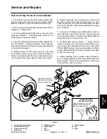
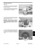
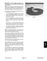
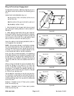
B. When installing NEW ring and pinion gears (sup-
plied in matched sets only) make sure the numbers
etched on both the pinion and ring gear match
(Fig. 27).
Compare the +, -, or 0 markings of the old and new
pinions. Adjust the thickness of a new shim pack to
compensate for the difference in these two numbers.
For example: If the old pinion reads +2 and the new
pinion reads -2, add 0.004 in. of bearing shims to the
original shim pack thickness.
NOTE: The following information is provided to help
you understand the adjustment required for proper en-
gagement of NEW ring and pinion gears.
To ensure proper engagement, an additional number is
etched into the button end of each pinion gear. This
number indicates modifications that must be made to
the “pinion to ring gear distance” for each particular gear
set. This distance is controlled by adding or removing
shims behind the inner bearing cup.
A pinion gear etched 0 is considered standard, and has
a 1.210 in. pinion to ring gear distance.
A pinion gear 3 requires a pinion to ring gear
distance of 1.213 in. (+0.003 in. from standard). Remov-
ing 0.003 in. of bearing shims moves the pinion gear
away from the ring gear, increasing the pinion to ring
gear distance.
A pinion gear etched -3 requires a pinion to ring gear dis-
tance of 1.207 in. (-0.003 in. from standard). Adding
0.003 in. of bearing shims moves the pinion gear closer
to the ring gear, decreasing the pinion to ring gear dis-
tance.
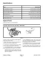
Figure 27
Содержание 00075SL
Страница 2: ...Reelmaster 5500 D ...
Страница 4: ...Reelmaster 5500 D ...
Страница 6: ...Reelmaster 5500 D ...
Страница 12: ...0 09375 Rev D Reelmaster 5500 D Page 2 2 Product Records and Maintenance Equivalents and Conversions ...
Страница 49: ...Hydraulic System Reelmaster 5500 D Hydraulic System Rev C Page 4 11 This page is intentionally blank ...
Страница 64: ...Reelmaster 5500 D Hydraulic System Rev C Page 4 26 This page is intentionally blank ...
Страница 89: ...Hydraulic System Reelmaster 5500 D Hydraulic System Rev C Page 4 51 This page is intentionally blank ...
Страница 109: ...Hydraulic System Reelmaster 5500 D Hydraulic System Rev C Page 4 71 This page is intentionally blank ...
Страница 115: ...Hydraulic System Reelmaster 5500 D Hydraulic System Rev C Page 4 77 This page is intentionally blank ...
Страница 170: ...Reelmaster 5500 D Page 5 40 Electrical System Rev C ...
Страница 192: ...Reelmaster 5500 D Differential Axle Page 6 22 ...
Страница 254: ...Reelmaster 5500 D Groomer Rev C Page 8 1 14 ...
Страница 278: ...Reelmaster 5500 D Page 10 2 Electrical Diagrams Rev C ...
Страница 284: ...Rev C Page 10 8 Harness Drawing Reelmaster 5500 D Serial Number 210000401 to 210999999 ...
Страница 285: ...Rev C Page 10 9 Harness Diagram Reelmaster 5500 D Serial Number 210000401 to 210999999 ...
Страница 286: ...Rev C Page 10 10 Harness Drawing Reelmaster 5500 D Serial Number 220000001 to 220999999 ...
Страница 287: ...Rev C Page 10 11 Harness Diagram Reelmaster 5500 D Serial Number 220000001 to 220999999 ...
Страница 288: ...Rev C Page 10 12 Harness Drawing Reelmaster 5500 D Serial Number Above 230000000 ...
Страница 289: ...Rev C Page 10 13 Harness Diagram Reelmaster 5500 D Serial Number Above 230000000 ...
Страница 290: ...Reelmaster 5500 D ...

