Differential
Axle
Rev. C
Reelmaster 5500-D
Differential Axle
Page 6 - 3
Service and Repairs
Axle Assembly Removal and Installation
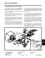
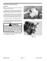
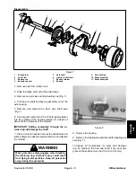
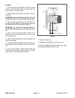
1. Put machine on a level surface, lower cutting units,
stop the engine and remove key from ignition switch.
Block rear wheels to prevent machine from moving.
2. Remove the cutting units (See the Repairs section of
Chapter 8 - Cutting Units).
3. If unit is equipped with 4WD, remove rear axle drive
shaft (see Chapter 9 - 4WD Rear Axle). Remove nut,
pinion spacer and pinion coupler.
4. Remove hydrostatic transmission (See Repairs sec-
tion of Chapter 4 - Hydraulic System). Keep transmis-
sion support attached to frame and gear pump attached
to transmission support.
5. Slightly loosen all front wheel lug nuts. Jack both
front wheels off the ground and install jackstands or
blocks under traction unit frame (not axle tubes) to pre-
vent machine from falling. Remove both front wheels.
6. Remove the cotter pin and clevis pin to disconnect
the brake cable from brake actuating lever on each
brake. Loosen jam nut to remove brake cable from each
end of axle bracket. Disconnect speedometer sensor
wire connector.
7. Put a jack or blocking under differential to hold it in
place. Remove cap screws and lock nuts securing axle
mounting pads to frame. Carefully lower differential axle
and pull it out from under traction unit.
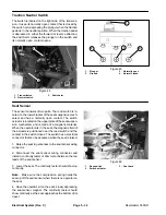
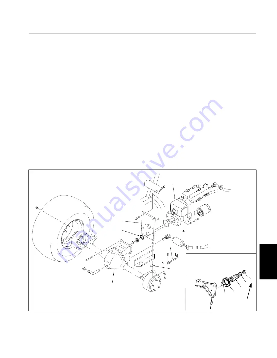
8. To install axle, reverse steps 1 - 7. Apply silicone
sealant between axle housing and transmission sup-
port. Leave axle mounting pad nuts loose. Install shims
(P/N 42-6080) between axle mounting pads and frame
to align differential with transmission support, then tight-
en axle mounting nuts.
9. Before installing pinion coupler, apply Permatex
No. 2 to external splines of pinion and internal splines of
pinion coupler. Torque nut securing pinion coupler from
75 to 90 ft-lbs. (102 to 122 Nm).
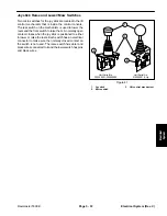
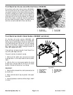
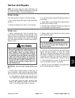
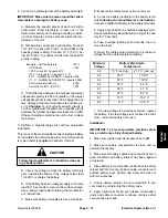
1. Hydrostatic
transmission
2. Transmission
support
3. Transmission
collar
4. Axle
shim
5. Differential
axle
6. Brake
cable
7. Nut
8. Spacer
9. Pinion
coupler
10. Seal
11. Shim
Figure 4
4
5
6
1
2
3
11
10
9
8
7
Coupler for 4WD
rear axle drive shaft
Apply Permatex No. 2 to outer
diameter of seal and internal
splines of pinion coupler
Apply silicone sealant
between axle housing and
transmission support
75 to 90 ft−lb
(102 to 122 Nm)
Содержание 00075SL
Страница 2: ...Reelmaster 5500 D ...
Страница 4: ...Reelmaster 5500 D ...
Страница 6: ...Reelmaster 5500 D ...
Страница 12: ...0 09375 Rev D Reelmaster 5500 D Page 2 2 Product Records and Maintenance Equivalents and Conversions ...
Страница 49: ...Hydraulic System Reelmaster 5500 D Hydraulic System Rev C Page 4 11 This page is intentionally blank ...
Страница 64: ...Reelmaster 5500 D Hydraulic System Rev C Page 4 26 This page is intentionally blank ...
Страница 89: ...Hydraulic System Reelmaster 5500 D Hydraulic System Rev C Page 4 51 This page is intentionally blank ...
Страница 109: ...Hydraulic System Reelmaster 5500 D Hydraulic System Rev C Page 4 71 This page is intentionally blank ...
Страница 115: ...Hydraulic System Reelmaster 5500 D Hydraulic System Rev C Page 4 77 This page is intentionally blank ...
Страница 170: ...Reelmaster 5500 D Page 5 40 Electrical System Rev C ...
Страница 192: ...Reelmaster 5500 D Differential Axle Page 6 22 ...
Страница 254: ...Reelmaster 5500 D Groomer Rev C Page 8 1 14 ...
Страница 278: ...Reelmaster 5500 D Page 10 2 Electrical Diagrams Rev C ...
Страница 284: ...Rev C Page 10 8 Harness Drawing Reelmaster 5500 D Serial Number 210000401 to 210999999 ...
Страница 285: ...Rev C Page 10 9 Harness Diagram Reelmaster 5500 D Serial Number 210000401 to 210999999 ...
Страница 286: ...Rev C Page 10 10 Harness Drawing Reelmaster 5500 D Serial Number 220000001 to 220999999 ...
Страница 287: ...Rev C Page 10 11 Harness Diagram Reelmaster 5500 D Serial Number 220000001 to 220999999 ...
Страница 288: ...Rev C Page 10 12 Harness Drawing Reelmaster 5500 D Serial Number Above 230000000 ...
Страница 289: ...Rev C Page 10 13 Harness Diagram Reelmaster 5500 D Serial Number Above 230000000 ...
Страница 290: ...Reelmaster 5500 D ...

