background image

1 NOMENCLATURE AND FUNCTIONS

1-9

1)

View Date & Time
The date and time can be viewed on both screens. To change the displayed order of the date,
(Date/Month/Year), (Month / Date / Year) or (Year/Month/Date), see Chapter 8 “PARAMETERS SET-
TING MODE” .
To set the date and time, see Chapter 9 “CHECK AND ADJUSTMENT”.

2)

Turn the auto-tracking ON/OFF (GPT-8000A series)
Press the [F1] key to start auto-tracking. See Section 3.1 “Automatic Tracking” .

3)

Turn the auto-collimating ON/OFF (GPT-8000A series)
Press the [F2] key to start auto-collimating. See Section 3.2 “ Automatic Collimation” .

4)

Set the parameters for the auto-tracking (GPT-8000A series)
A proper setting for each parameter such as tracking pattern, tracking range, waiting time, track-
ingspeed and tracking sensitivity. See Section 3.4 “Setting Parameters for 
Auto-Tracking” .

5)

Auto Inversion
Pressing the [F4] key causes the instrument to reverse and turn the telescope and 
instrument automatically.

• To stop auto rotating in case of emergency, press any keys except POWER key.
• During auto rotation, do not disturb the instrument.(Stopping the rotation with a touch of the hand). 

Such action may cause trouble or harm to instrument or operator.

6)  Adjustment the contrast of the display

This enable you to adjust the contrast of the display.
Press the [F6] key to get to Screen 2 on the display.
Press the [F1] or [F2] key to brighten or dim the display.
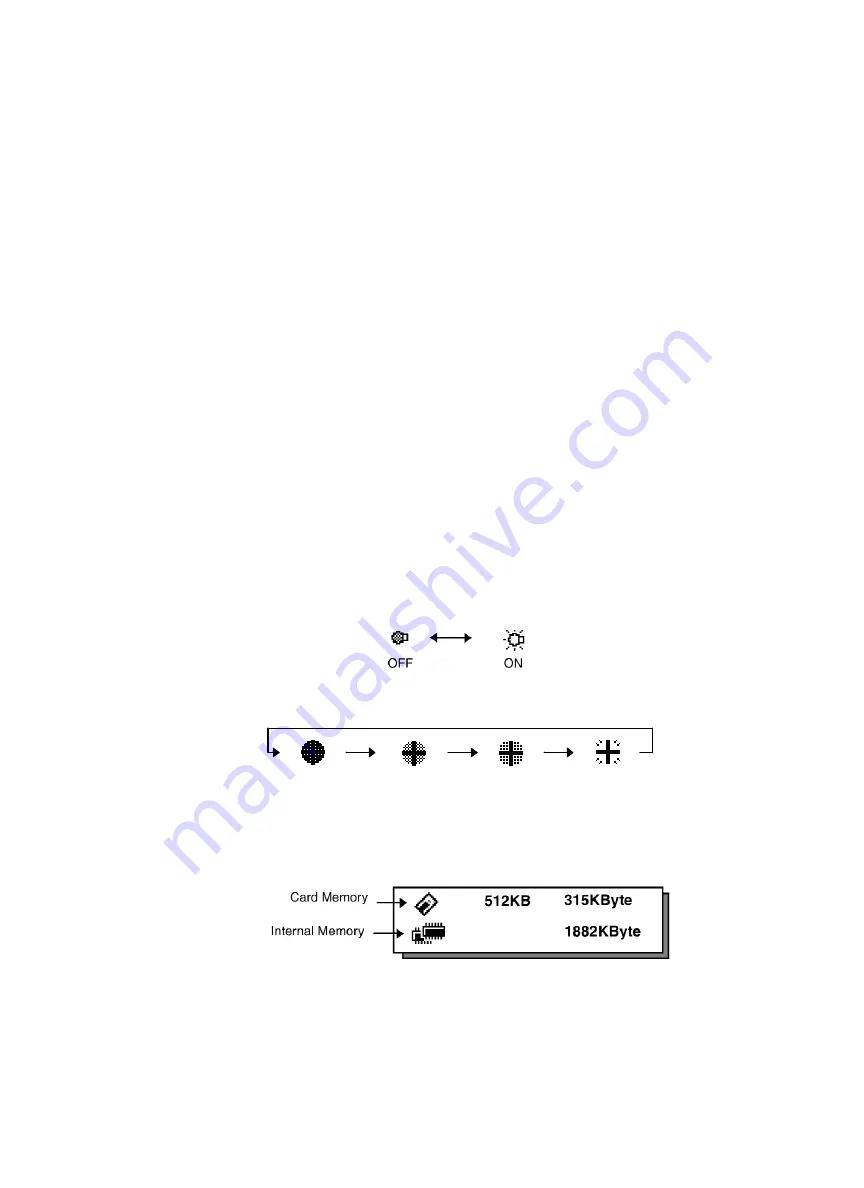
7)

Turn the display back light ON/OFF
When the back light is OFF, the light bulb icon is dark.
Press the [F6] key to get to Screen 2 on the display.
To turn the back light ON, press the [F3] key. Press [F3] again to turn the back light OFF.

8)

Reticle illumination (OFF/Low/Middle/High)
Press the [F6] key to get to Screen 2 on the display. Press the [F4] key to turn the reticle illumination
ON. Continuing to press [F4] will change the intensity options.

9)

View free memory
The amount of free memory for the card or internal memory can be displayed.
Press the [F6] key to get to Screen 2 on the display.
Press the [F5] key to view free memory.
The card memory icon (top left side of the display) shows the size of the card and the amount of free
memory. The second icon shows the amount of free internal memory.

See Chapter 6 “MEMORY MANAGE MODES”, for further options and instructions.

Low

OFF

Middle

High

Содержание GPT-8000 Series

Страница 1: ...INSTRUCTION MANUAL AUTOMATIC TRACKING PULSE TOTAL STATION GPT 8000A SERIES GPT 8001A GPT 8002A GPT 8003A GPT 8005A GPT 8001 GPT 8002 GPT 8003 GPT 8005 GPT 8000 SERIES SERVO PULSE TOTAL STATION ...

Страница 2: ... Phone 44 1635 551120 Fax 44 1635 551170 survey sales topcon co uk laser sales topcon co uk TOPCON SOUTH ASIA PTE LTD Blk 192 Pandan Loop Pantech Industrial Complex 07 01 Singapore 128381 Phone 62780222 Fax 62733540 www topcon com sg TOPCON AUSTRALIA PTY LTD 408 Victoria Road Gladesville NSW 2111 Australia Phone 02 9817 4666 Fax 02 9817 4654 www topcon com au TOPCON INSTRUMENTS THAILAND CO LTD 77 ...

Страница 3: ...ing screws are tightened Guarding the instrument against shocks When transporting the instrument provide some protection to minimize risk of shocks Heavy shocks may cause the measurement to be faulty Carrying the instrument Always carry the instrument by its handgrip Exposing the instrument to extreme heat Do not leave the instrument in extreme heat for longer than necessary It could adversely aff...

Страница 4: ...o align its mark with the lower base mark Storage mark Keep its objective lens side downward Storing it in the case in any other way may cause damage Hold the hand grips and base with both hands when taking the instrument out of the case or putting the equipment in the case Maintenance for driving parts Every 4 000 5 000 hours operation in total change grease of driving parts Contact your dealer o...

Страница 5: ...e eye injury or blindness Do not stare into beam GPT 8000A series and laser plummet model High temperature may cause fire Do not cover the charger while it is charging High temperature may cause fire Do not connect the battery to an instrument while it is charging Risk of fire or electric shock Do not use damaged power cable plug and socket Risk of fire or electric shock Do not use a wet battery o...

Страница 6: ...ll over It could be dangerous if the instrument falls over please check that you fix the instrument to the tripod correctly Risk of injury by falling down a tripod and an instrument Always check that the screws of tripod are tightened User 1 This product is for professional use only The user is required to be a qualified surveyor or have a good knowledge of surveying in order to understand the use...

Страница 7: ...s classified as Class 1 l Laser Products In case of any failure do not disassemble the instrument Contact TOPCON or your TOPCON dealer GPT 8000A series GPT 8000A series uses the visible laser beam for auto tracking and optical communication The GPT 8000A series products are manufactured and sold in accordance with Radiation Safety of Laser Products Equipment Classification Requirements and User s ...

Страница 8: ...dealer Labels The following labels are found on the instruments which describe the GPT 8000A 8000 series Laser plummet type Precautions and safety information about the laser beam If at any time any of these labels are damaged and become illegible please replace these important labels Please the new labels in exactly the same position as the original labels Replacement labels can be obtained from ...

Страница 9: ...nstrument 2 7 2 8 Resume Mode ON OFF 2 8 2 9 How to Enter Numerals and Alphabet Letters 2 8 2 10 Memory Card 2 9 2 11 Inclination of Prism and Measuring Error GPT 8000A series 2 10 3 AUTOMATIC TRACKING AUTOMATIC COLLIMATION GPT 8000A series 3 1 3 1 Automatic Tracking 3 1 3 2 Automatic Collimation 3 3 3 3 Range of Laser for Auto tracking and Auto collimating 3 4 3 4 Setting Parameters for Auto Trac...

Страница 10: ...r Setting Options 8 1 8 1 1 Parameters for Measurement and Display 8 1 8 1 2 Parameters for communication 8 2 8 2 Setting Parameters 8 4 8 2 1 Parameters for Measurement and Display 8 4 8 2 2 Parameters for Communication 8 5 8 2 3 Password Option 8 6 9 CHECK AND ADJUSTMENT 9 1 9 1 Checking and Adjusting of Instrument Constant 9 1 9 1 1 Checking of the accuracy of the non prism mode 9 1 9 2 Checkin...

Страница 11: ...Precaution when Charging or Storing Batteries APPENDIX 3 Standard Set Composition 1 GPT 8000A 8000 series with lens cap 1 each 2 Battery BT 56Q 1 each 3 Battery charger BC 27BR or BC 27CR 1 each 4 Tool kit with case rod pins screwdriver cleaning brush 1 set 5 Plastic carrying case 1 each 6 Silicon cloth 1 each 7 Plastic rain cover 1 each 8 Instruction manual 1 each Make sure that all of the above ...

Страница 12: ...ial Signal Connector 1 6pin Sighting collimator Handle fixing knob Display window Operation keys Battery BT 56Q Card cover lever Instrument height mark Tracking indicator GPT 8000A series Point guide GPT 8000 series Laser aperture for optical communication GPT 8000A series The caution labels are pasted up GPT 8000A series and Laser plummet model which describe the warning of laser beam Refer to La...

Страница 13: ...Telescope grip Telescope eyepiece Instrument center mark Battery fixing knob Vertical shuttle Vertical jog Horizontal shuttle Horizontal jog Adjusting screws for circular level Instrument height mark Centronics connector Tribrach fixing lever Circular level Power switc h ...

Страница 14: ...information Rotation Indicator Refer to Section 1 8 Rotating Method for further information Laser plummet is working Only for laser plummet model 1 2 Display Display In general upper four lines display the measuring data and the bottom line displays the soft key function which is changed by the measuring mode Contrast The contrast and illumination of display window are adjusted by star key Heater ...

Страница 15: ...eries is searching a prism Failure in auto collimating Laser is off GPT 8000A series could not find the target prism during auto collimating KEY NAME FUNCTION F1 F6 Soft key Functions are according to the displayed message 0 9 Numeric key Numeric Character Entry for Preset Data A Alpha key Alpha Character Entry ESC Escape key Escape to Previous Display or Menu Star key Optional instrument function...

Страница 16: ... ON the display shows tilt correction value Horizontal distance measuring Coordinate measuring Angle measuring Slope distance measuring TURN HT MEAN P2 REC SO MEAN P2 TURN SO MEAN m ft P2 TURN HSET R L V TILT P2 Soft keys V 87 55 45 5 HR 180 44 12 5 SD HD NEZ 0SET HOLD P1 F1 F2 F3 F4 F5 F6 V 87 55 45 5 HR 180 44 12 5 SD HD NEZ 0SET HOLD P1 V 90 10 20 5 HR 120 30 40 5 PSM 0 0 HD PPM 0 0 VD m F R ME...

Страница 17: ... 10mm mode VH F3 Angle measurement mode SD F4 Slope distance measuring mode Display the slope distance after N times or single measurement NEZ F5 Coordinate measurement mode Displays the coordinate after N times or single measurement TURN F1 Turns the instrument to required angle automatically SO F2 Stake out measurement mode MEAN F3 Sets the number of N time measurement m ft F4 Switches meter or ...

Страница 18: ...ght acceptance quantity level signal level is displayed F1 12 Set the Temperature Pressure Atmospheric Correction Value PPM and Prism Constant Value PSM F2 13 Turn the Tracking Indicator option ON OFF F3 14 Electric circular graphic display F5 15 Turn the Laser plummet option ON OFF F5 only for Laser plummet model 1 NOMENCLATURE AND FUNCTIONS 1 7 2002 07 07 14 30 40 1 2002 07 07 14 30 40 2 Back Li...

Страница 19: ...pe NP P Point guide Non prism Prism mod e GPT 8000A Series Screen One 1 View Date Time 2 Electric circular graphic display F1 3 The light acceptance quantity level signal level is displayed F2 4 Set the Temperature Pressure Atmospheric Correction Value PPM and Prism Constant Value PSM F3 5 Auto inversion F4 6 Non prism mode Prism mode selection F5 Screen Two 7 Adjustment the contrast of the displa...

Страница 20: ...do not disturb the instrument Stopping the rotation with a touch of the hand Such action may cause trouble or harm to instrument or operator 6 Adjustment the contrast of the display This enable you to adjust the contrast of the display Press the F6 key to get to Screen 2 on the display Press the F1 or F2 key to brighten or dim the display 7 Turn the display back light ON OFF When the back light is...

Страница 21: ...000A series Operation Pressing F3 key on the screen three functions Tracking Indicator The tracking indicator status will be changed according to the type of auto tracking mode and its conditions A man from the prism side can recognize the status of instrument When angle measuring value turns stable during tracking still object the tracking indicator changes from quick continuous flashing to quick...

Страница 22: ...28 ft The quality of its results will depend on the weather conditions and the use s eyesight The goal of the rod person is to look at both LEDs on the instrument and move the prism on line until both LEDs become equally bright If the solid LED is brighter move to the right If the blinking LED is brighter move to the left 14 Electric circular level graphic display Electric circular level can be di...

Страница 23: ...time See Chapter 8 PARAMETERS SETTING MODE for further instructions 1 7 Data Output When GPT 8000A 8000 series receives data output command from an external connected device the measured data will be output by GPT 8000A 8000 series Select from the following 2 ways for the output For setting see Chapter 8 PARAMETERS SETTING MODE REC A The measurement is started and new data is output REC B The data...

Страница 24: ...ions see Section 4 1 5 Automatic Rotation to a Required Horizontal and Vertical Absolute Angle Attaching Precaution Label Attach 4 precaution labels to the instrument in specified places to avoid the unexpected accident such as pinching fingers between telescope and body of instrument or telescope and hand grip during automatic rotation This mark will appear while the instrument is rotating automa...

Страница 25: ... controller you can manage communication reciprocally between the instrument and direct to data collector Turn round function You can turn the GPT 8000A series round to the remote controller RC 2II side easily by Turn round key of the remote controller RC 2II This function helps to increase one man surveying efficiency See to Section 5 7 External Link GPT 8000A series and Chapter 8 PARAMETERS SETT...

Страница 26: ...r measured data Each measured data will be out put according to the command type Transmit command for tracking mode The status of Automatic Tracking mode will be out put Transmit command for battery level The battery level will be out put Transmit command for coordinate of instrument point Setting coordinate of instrument point will be out put Transmit command for tracking parameter Each setting t...

Страница 27: ...d Large capacity battery pack BT 3L Power cord PC 6 is used When using a external battery the rechargeable battery BT 56Q should be attached The instrument will lack in balance if the internal battery BT 56Q is removed The external battery and the internal battery can be used at the same time The GPT 8000A 8000 series will select a battery due to the battery remaining automatically Connector ends ...

Страница 28: ...rument horizontally by using the Horizontal motion clamp screw and place the plate level parallel with the line connecting leveling screws A and B and then bring the bubble to the center of the plate level by turning leveling screws A and B 2 Rotate the instrument 90 100g around its vertical axis and turn the remaining leveling screw or C to center the bubble once more 3 Repeat the procedures 1 an...

Страница 29: ...d memorized After checking the main menu icons will be shown Battery Power Remaining Display Self checking option The self checking function is to check internal communication and tilt sensor offset value When ambient temperature is changed or the instrument is not balanced by its internal battery is attached or detached the self checking is recommended Password option Setting a password Maximum 1...

Страница 30: ...battery 2 In low temperature especially while the heater of display is working the battery operating time will shorten to one half of normal temperature use 3 The indicator for battery power remaining shows the power level during each measurement mode The condition indicated for the battery power remaining in the angle measurement mode may not be adequate to measure a distance Changing from angle ...

Страница 31: ...A series See Chapter 9 CHECK AND ADJUSTMENT COMMUNICATION MODES Set communication with external instrument Input Output a data file See Chapter 7 COMMUNICATION MODES MEMORY MANAGE MODES Display memory status Protect Eras Rename Copy Files Initialize a card or internal memory See Chapter 6 MEMORY MANAGE MODES 2 6 STANDARD MEASUREMENT MODES Angle measurement Distance measurement Coordinate measureme...

Страница 32: ... Trunnion axis Horizontal GPT 8000A 8000 series compensates both the vertical angle and the horizontal angle readings due to inclination of the standing axis in the X and Y directions For more information about dual axis compensation see Chapter APPENDIX Dual Axis Compensation The display of Vertical or Horizontal angle is unstable when instrument is on an unstable stage or a windy day You can tur...

Страница 33: ...o far To adjust or reset the above compensation value see Chapter 9 CHECK AND ADJUSTMENT Enable you to stop this function see Chapter 8 PARAMETERS SETTING MODE or Chapter 9 CHECK AND ADJUSTMENT Operating procedure Option Display 1 Press F6 key to get the function page 2 F6 2 Press F5 TILT key Current setting is displayed 1 F5 3 Press F2 ON 2 key The display shows tilt correction value F2 4 Press F...

Страница 34: ...y select the resume mode F1 F2 Power off Resume mode OFF ON ESC Power switch key OFF Operating procedure Option Display 1 Press F1 Alpha key to be entering alphabet letter mode F1 2 Enter Alphabets 1 Type H Move cursor Type I T ype L T ype 9 9 F4 9 9 9 4 4 4 3 3 3 3 Press F1 Num key to be entering numeric mode Input 104 F1 1 0 4 4 Press ENT when complete ENT 1 When the same alpha key is to be type...

Страница 35: ...mory Card How to insert a memory card 1 Pull the card cover lever to open the card cover 2 Insert a memory card until the card guide is up 3 Close the card cover How to extract a memory card 1 Pull the card cover lever to open the card cover 2 Pull down the card guide 3 Extract the memory card ...

Страница 36: ...re error in measurement Measured data can be different according to the prism constant value This can occur when a prism is moving Pin pole prism set L1 for one person surveying and pin pole prism holder L1 for fixed point observa tion are designed to minimize measuring error in such case Make the best use of them In case you are forced to use the normal prism in inclined state because there is no...

Страница 37: ...or range Distance Measuring error Angle measuring error Inclined angle degree Inclined angle degree mm mm Example In case Prism constant value C 0mm Prism inclination 20 Measuring distance 100m by Prism type 2 Distance error is From the graph prism type 2 the distance error shows in increasing range quantity 2 5mm along curved line of C 0 when prism inclination is 20 Angle error is From the graph ...

Страница 38: ...G Cause eye injury or blindness Do not stare into beam CAUTION Let the laser beam reach the aimed object or the target without anybody else in the laser beam path In case you operate laser beam open avoid radiating laser beam to the height of man s head It is quite possible for the beam to enter into one s eyes and it is possible to lose visual sight temporarily and lose one s caution and awarenes...

Страница 39: ...sometimes can be unstable for a few seconds after the optical path is disturbed If the center of reticle and the center of the prism is not coincided you should adjust optical axis for auto tracking refer to chapter 9 Check and adjustment In the not suitable operating condition in such the atmospheric condition is not good by the heat shimmer or other bad weather condition in the long distance of ...

Страница 40: ...ating is finished the instrument does not track the prism even if the prism is moved The auto tracking can be done correctly in the time of shaking prism or in bad weather condition is not good by the heat shimmer The above caution mark will be displayed after 10 seconds and the auto tracking will be finished V 87 55 45 HR 180 44 12 SD HD NEZ 0SET HOLD P1 2002 07 07 14 30 40 1 NP P V 87 55 45 HR 1...

Страница 41: ...e is within 30 as shown in following So you had better colli mate the prism so that the prism may be located within this range of laser in the first step As for it rapid automatic collimating and automatic tracking becomes possible If the target prism is out of this range time for searching mode will be necessary Field of view about 30 about 30 Range of laser ...

Страница 42: ...lected REFRECTOR T APE 1 Search Patterns The search pattern is the rotating method of telescope and instrument to find the target prism in search mode Search pattern includes the following 2 ways that can be selected PATTERN 1 This pattern can be selected to search the prism at the point where the prism is lost Instrument searches in up down direction gradually from the point where the prism is lo...

Страница 43: ...rections horizontal and vertical 3 Wait Time The time the prism is lost before GPT 8000A series starts the searching Setting time is 1second step maximum 60 minutes If the mode is set to HOLD mode will not change to searching 4 Tracking Speed The tracking accuracy aiming accuracy shall be determined in the best condition by the relation ship of moving speed of the prism and the distance between GP...

Страница 44: ...3 3 Press the F6 P1 key to get the menu on page 2 F6 4 Press the F1 TRK SPEED key F1 5 Press the F6 key to select MACHINE CONTROL 6 Press the ENT key to decide F6 ENT 2002 07 07 14 30 40 1 NP P F1 SEARCH PATTERN F2 SEARCH RANGE F3 WAIT TIME P1 F1 TRK SPEED F2 REFLECTOR TYPE P1 TRACKING SPEED SURVEY TRACKING SPEED MACHINE CONTROL 3 4 2 How to set the parameters Sample setting Set TRACKING SPEED to ...

Страница 45: ...LD P1 Reference How to Collimate 1 Point the telescope toward the light Turn the diopter ring and adjust the diopter so that the cross hairs are clearly observed Turn the diopter ring toward you first and then backward to focus 2 Aim the target at the peak of the triangle mark of the sighting collimator Allow a certain space between the sighting collimator and yourself for collimating 3 Focus the ...

Страница 46: ...ches HR HL switching can be turned OFF Refer to Chapter 8 PARAMETERS SETTING MODE V 87 55 45 HR 120 30 40 SD HD NEZ 0SET HOLD P1 TURN HSET R L V TILT P2 V 87 55 45 HL 239 29 15 PSM 0 0 PPM 0 0 m F R TURN HSET R L V TILT P2 Operating procedure Operation Display 1 Set the required horizontal angle using Horizontal jog shuttle Display angle 2 Press F5 HOLD key F5 3 Collimate the target 1 Collimate 4 ...

Страница 47: ...F6 BS key or input from the beginning by F1 EXIT key to correct value 2 With wrong input value for example 70 setting will not be completed Input again from step 3 V 90 10 20 HR 120 30 40 SD HD NEZ 0SET HOLD P1 TURN HSET R L V TILT P2 H SET HR H SET HR 70 203 EXIT BS V 90 10 20 HR 70 20 30 SD HD NEZ 0SET HOLD P1 4 1 4 Vertical Angle Percent Grade Mode Make sure the mode is Angle measurement Operat...

Страница 48: ...V angle ENT H angle ENT 5 Input the horizontal angle to be rotated and press ENT key For example 160 20 10 The instrument will start to rotate 2 When the instrument has finished rotating 3 the instrument will return to the previous mode 1 Setting range for rotation is 0 00 00 HR 359 59 59 0 00 00 V 359 59 59 2 Press any key except power key to stop rotating in emergency during operation 3 You can ...

Страница 49: ...be done before measurement If happened collimating the near distance prism in Non prism mode measurement will not be done because of too much light V 90 10 20 5 NP HR 120 30 40 5 NPM 0 0 HD PPM 0 0 VD m F R MEAS MODE VH SD NEZ P1 Non prism mode indicator Distance measurement mode Example Non prism constant valu 4 2 1 Setting of the Atmospheric Correction When setting the atmospheric correction obt...

Страница 50: ...Fine meas mode C Coarse 1mm meas mode c Coarse 10mm meas mode R Continuous Repeat meas mode S Single meas mode N N time meas mode 2 When EDM is working the mark appears in the display 3 The result is shown with buzzer sound 4 Measurement may repeat automatically if the result is affected by shimmer etc 5 To change single measuring press F1 MEAS key 6 To return to the angle measurement mode press F...

Страница 51: ... F2 HD key 2 Press F6 key to get the function page as 2 F2 F6 3 Press F3 MEAN key F3 4 Input the setting the number of times and press ENT key 1 Example 4 times N times measurement starts F4 ENT V 90 10 20 HR 120 30 40 SD HD NEZ 0SET HOLD P1 V 90 10 20 HR 120 30 40 PSM 0 0 HD PPM 0 0 VD m F R MEAS MODE VH SD NEZ P1 REC SO MEAN m ft P2 Average times N 0 EXIT BS V 90 10 20 HR 120 30 40 PSM 0 0 HD PP...

Страница 52: ... re measuring after the measurement in held To return to the continuous measuring press F1 MEAS key twice To return to the angle measuring mode press F3 VH key V 90 10 20 HR 120 30 40 PSM 0 0 HD 54 321 PPM 0 0 VD 1 234 m F N MEAS MODE VH SD NEZ P1 V 90 10 20 HR 120 30 40 PSM 0 0 HD 54 321 PPM 0 0 VD 1 234 m F MEAS MODE VH SD NEZ P1 ...

Страница 53: ...ect or carrying out stake out work Measurement time approx 0 3 seconds The unit to be displayed is 10mm 0 02ft Operating procedure Operation Display 1 Collimate the center of prism Collimate 2 Select the measurement mode by pressing F1 SD or F2 HD key Example Horizontal distance Measuring starts F2 3 Press F2 MODE key the mode changes to Coarse mode Press F2 MODE key again the mode changes to Trac...

Страница 54: ...orizontal distance HD relative elevation VD or slope distance SD Example Relative elevation Operating procedure Operation Display 1 Press F6 P1 key in the distance measuring mode to get the function as in page 2 F6 2 Press F2 S O key and press ENT key 3 Enter the relative elevation for stake out and press ENT key The measuring starts F2 ENT Enter value ENT 4 Collimate the target Prism The differen...

Страница 55: ...coordinates will be retained only if you choose Resume ON when shutting the power OFF For instructions on how to select NEZ memory ON OFF refer to Chapter 8 PARAMETERS SETTING MODE N E z n e Prism n e z Inst PointC Origin 0 0 0 Confirm the angle measurement mode Operating procedure Operation Display 1 Press F3 NEZ key 2 press F6 key to get the function as on page 2 F3 F6 3 Press F5 SET key The pre...

Страница 56: ...t new data and press ENT key 1 Measuring starts N coord ENT E coord ENT Z coord ENT 1 To cancel the setting press F1 EXIT key Setting occ point N 0 0000 E 0 0000 Z 0 0000 EXIT BS Complete N E PSM 0 0 Z PPM 0 0 m F R TURN HT MEAN m ft SET P2 ...

Страница 57: ...y 2 Press F6 key from the coordinate measurement mode to get the function as in page 2 F3 F6 3 Press F2 HT key to type in the instrument and prism height Previous data will be shown F2 4 Input instrument height and press ENT key 1 Inst HT ENT 5 Input prism height and press ENT key The display returns to coordinate measuring mode Prism HT ENT 1 To cancel the setting press F1 EXIT key V 90 10 20 HR ...

Страница 58: ...ertical distance Relative elevation z Coordinates of the center of the prism originated from the center point of the instrument n e z Coordinates of unknown point N 1 E 1 Z 1 N 1 N 0 n E 1 E 0 e Z 1 Z 0 Inst h z P h Confirm the angle measurement mode Operating procedure Operation Display 1 Set coordinates values of occupied point and instrument prism height 1 2 Set the direction angle of known poi...

Страница 59: ...not set 3 Refer to Section 4 1 3 Measuring from the Required Horizontal Angle or Section 4 1 3 Measuring from the Required Horizontal Angle 4 Pressing F1 MEAS key the measurement mode Continuous measuring N time measuring changes Pressing F2 MODE key the measurement mode FINE COARSE 1mm COARSE 10mm changes To return to the normal angle or distance measuring mode press F6 P2 key to return to the fu...

Страница 60: ...utomatically return to the distance measurement mode Mode Output Angle mode V HR or HL V in percent V HR or HL Horizontal distance mode V HR HD VD V HR HD VD Slope distance mode V HR SD V HR SD HD Coordinate mode N E Z HR V 90 10 20 HR 120 30 40 PSM 0 0 HD PPM 0 0 VD m F R MEAS MODE VH SD NEZ P1 V 90 10 20 HR 120 30 40 PSM 0 0 HD 10 1234 PPM 0 0 VD 1 234 m F R REC V 90 10 20 HR 120 30 40 PSM 0 0 H...

Страница 61: ...ction measurement will be continued whenever tilt over The tilt over will not be compensated here In case tilt over the tilt information will be displayed on the upper right screen as the following marks during the utility function is selected Marks Status of tilt t Under tilt compensation Tilt Over Tilt OFF V 90 10 20 t HR 120 30 40 PSM 0 0 HD PPM 0 0 VD m c R MEAS MODE VH SD NEZ P1 Tilt informat...

Страница 62: ... OFFSET p MORE F6 MORE key Programs F1 LINE p 7 7 F2 OFFSET p F3 EXT LINK p MORE GPT 8000 series GPT 8000A seri es PROGRAM MODE APPLICATION MEASUREMENT 1 Setting a Horizontal Angle 2 Retaining a Coordinate STORE NEZ 3 Remote Elevation Measurement REM 4 Missing Line Measurement MLM 5 Line Measurement LINE 6 Offset Measurements OFF SET 7 External Link only for GPT 8000A series ...

Страница 63: ...be displayed 1 F1 2 Press F6 OK key 3 Input N and E coordinate of backsight point A Example N coordinate 54 321m E coordinate 12 345m F6 N data ENT E data ENT 4 Sight backsight point A 5 Press F5 YES key The display returns to main menu F5 1 If you need to change the occupied point data press F1 INP key and input new data N Direction angle Backsight point A E Instrument point C Programs F1 BS p 4 ...

Страница 64: ...erating procedure Operation Display 1 Press F2 STORE key F2 2 Press F1 Store NEZ key 1 F1 3 Collimate target P1 prism which the instrument moves Collimate P1 4 Press F1 MEAS key Measuring will start F1 Horizontal distance and horizontal angle are shown Origin 0 0 0 P3 P2 P1 N Direction angle Known point A E Inst point P0 Programs F1 BS p 4 7 F2 STORE p F3 REM p F4 MLM p MORE Retaining Coordinate 1...

Страница 65: ... Press F2 STORE key F2 9 Press F2 Recall NEZ key 10 Collimate P0 the former instrument point F2 Collimate P0 11 Press F5 YES key F5 The coordinates at P1 and direction angle toward P0 are set The display return to main menu 12 Repeat the procedure 1 11 as much as you wish 1 To reset the instrument height or prism height press F5 HT key Store NEZ N 123 456 m E 12 345 m Z 1 234 m SET OK YES NO Compl...

Страница 66: ...h input Example h 1 5m Operating procedure Operation Display 1 Press F3 REM key F3 2 Press F1 YES key F1 3 Enter prism height press ENT key Enter P HT ENT 4 Collimate prism Collimate P 5 Press F1 MEAS key Measuring starts F1 T arget K Prism P Prism height G Instrument VD Programs F1 BS p 4 7 F2 STORE p F3 REM p F4 MLM p MORE REM Prism height 1 YES 2 NO REM 1 Prism Height P h m EXIT BS REM 2 Horizo...

Страница 67: ...enu press F1 EXIT key Operating procedure Operation Display 1 Press F3 REM key F3 2 Press F2 NO key F2 3 Collimate prism 4 Press F1 MEAS key Measuring starts Collimate P F1 Horizontal distance HD between the instrument and prism will be shown REM 2 Horizontal Distance HD 123 456 m MEAS SET REM VD 0 234 m EXIT P h HD SET REM VD 1 456 m EXIT P h HD Programs F1 BS p 4 7 F2 STORE p F3 REM p F4 MLM p M...

Страница 68: ...nt G will be decided 1 F6 8 Collimate target K Vertical distance VD will be shown 2 Collimate K 1 To return to procedure 3 press F2 HD key To r eturn to procedure 6 press F3 V key 2 To return to main menu press F1 EXIT AND F5 YES key REM 2 Vertical Angle V 120 30 40 SET REM 2 Vertical Angle V 95 30 40 SET REM VD 0 000 m EXIT HD V REM VD 9 876 m EXIT HD V ...

Страница 69: ...ent is A B A C A D 2 A B B C Measurement is A B B C C D Example 1 A B A C Procedure of 2 A B B C mode is completely same as MLM 1 mode Operating procedure Operation Display 1 Press F4 MLM key F4 2 Press F1 A B A C key F1 Prism A Prism B Prism C Instrument Programs F1 BS p 4 7 F2 STORE p F3 REM p F4 MLM p MORE Missing Line Measurement 1 A B A C 2 A B B C MLM 1 Horizontal Distance 1 HD m MEAS SET ...

Страница 70: ...tween prism A and B F6 7 To measure the distance between points A and C press F2 HD key 1 F2 8 Collimate point C Prism C and press F1 MEAS key Horizontal distance HD between the instrument and prism C will be shown Collimate C F1 MLM 1 Horizontal Distance 1 HD m MEAS SET MLM 1 Horizontal Distance 1 HD 123 456 m MEAS SET MLM 1 Horizontal Distance 2 HD m MEAS SET MLM 1 Horizontal Distance 2 HD m MEA...

Страница 71: ...ion dVD and slope distance between prism A and C F6 10 To measure the distance between points A and D repeat procedure 7 to 9 1 1 To return to main menu press F1 EXIT and F5 YES key MLM 1 Horizontal Distance 2 HD 246 912 m MEAS SET MLM 1 dHD 123 456 m dVD 12 345 m dSD 12 456 m EXIT HD ...

Страница 72: ...ms menu to get the next page of programs F6 2 Press F1 LINE key F1 3 Press F1 YES key F1 4 Input the prism height and press ENT key Input P h ENT HD VD P h Prism A Off G L Prism B Instrument LH Programs F1 BS p 4 7 F2 STORE p F3 REM p F4 MLM p MORE Programs F1 LINE p 7 7 F2 OFFSET p F3 EXT LINK p MORE LINE Prism height 1 YES 2 NO LINE Prism height P h m EXIT BS LINE STEP 1 PT A HD m MEAS SET ...

Страница 73: ...ata to the line point L is displayed VD Vertical distance HD Horizontal distance from the instrument to L Off Horizontal distance from A to L Sight L 10 Press F2 LH key This function is used when measuring the line height from the ground The procedure is as follows Sight the point on the line before pressing this key Don t move the horizontal tangent screw by setting ground point G F2 LINE STEP 1 ...

Страница 74: ...finish the measurement press the F1 EXIT or ESC key To return to operation procedure 9 press the F2 VD key To return to operation procedure 11 press the F6 NEXT key The NEXT key is used when the ground point G is not clear and you would like to check another ground point G on the same vertical line LINE G POINT V 90 40 20 EXIT SET LINE LH 33 765 m Off 27 521 m EXIT VD NEXT ...

Страница 75: ...T 4 COLUMN OFFSET ANGLE OFFSET HR 87 55 45 HD 20 000 m VD 5 000 m NEXT SD NEZ REC F4 REC ANGLE OFFSET HR 87 55 45 HD 20 000 m VD 5 000 m REC YES NO F5 YES ANGLE OFFSET HR 87 55 45 HD 20 000 m VD 5 000 REC m Outputting the Measurement Data The results of offset measurement can be output to external device In offset measurement mode the F4 soft key which assigned REC will appear in measured r esult ...

Страница 76: ... Point When measuring coordinates of ground point A1 Set the instrument height prism height When measuring coordinates of point A0 Set the instrument height only Set the prism height to 0 When sighting to A0 you can select one of two ways HOLD is to fix vertical angle to the prism position even updown the telescope position and FREE is to gear vertical angle to the updown of telescope movement In ...

Страница 77: ...A0 press the F2 SD key F2 8 To show the coordinates press the F3 NEZ key 2 F3 1 To set the prism height or instrument height press the F5 HT key 2 To repeat angle offset measurement press the F1 NEXT key The display will return to step 5 ANGLE OFFSET HD m MEAS HT ANGLE OFFSET HD m MEAS HT ANGLE OFFSET HR 20 3 0 40 HD 20 000 m VD 0 000 m NEXT SD NEZ REC ANGLE OFFSET HR 30 0 0 00 HD 20 000 m VD 0 00...

Страница 78: ...g procedure Operation Display 1 Press F6 MORE key from programs menu to get to the next page of programs F6 2 Press F2 OFFSET key F2 3 Press F2 DIST OFFSET key Previous offset value screen will appear dFR Forward Rear offset value dRL Right Left offset value F2 A 1 A0 oHD sign Forward HD RorL HD Prism height Prism P Occ Point Instrument height Programs F1 BS p 4 7 F2 STORE p F3 REM p F4 MLM p MORE...

Страница 79: ...SD key F2 7 To show the coordinates press the F3 NEZ key 3 F3 1 To skip the input press the F1 OK key 2 To set the prism height or instrument height press the F5 HT key 3 To repeat the offset measurement press the F1 NEXT key The display will return to step 5 DIST OFFSET dFR 0 000 m dRL 0 000 m EXIT BS DIST OFFSET HD m MEAS HT DIST OFFSET HR 30 0 0 00 HD 20 000 m VD 0 000 m NEXT SD NEZ REC DIST OF...

Страница 80: ...d distance value of cross point between collimation axis and of the plane Operating procedure Operation Display 1 Press F6 MORE key from programs menu to get to the next page of programs F6 2 Press F2 OFFSET key F2 3 Press F3 PLANE OFFSET key Measurement screen of three points on a plane will be shown F3 P P P2 3 P Target heights of P1 to P3 is set to zero automatically Edge Prism Prism Prism Poin...

Страница 81: ...o show the coordinates press the F3 NEZ key 3 4 F3 1 In case the calculation of plane was not successful by the measured three points error displays Start measuring over again from the first point 2 Error will be displayed when collimated to the direction which does not cross with the determined plane 3 The reflector height of the target point P0 is set to zero automatically 4 To repeat the offset...

Страница 82: ... F6 2 Press F2 OFFSET key F2 3 Press F4 COLUMN OFFSET key Measurement screen of the center of a column will be shown F4 4 Collimate the center of the column P1 and press the F1 MEAS key Measuring will start After the measurement angle measuring display of the left side P2 will be shown Collimate P1 F1 P P P 2 3 P Prism Programs F1 BS p 4 7 F2 STORE p F3 REM p F4 MLM p MORE Programs F1 LINE p 7 7 F...

Страница 83: ... and center of the column P0 will be calculated and displayed Collimate P3 F6 7 To show the slope distance of point P0 press the F2 SD key F2 8 To show the coordinates press the F3 NEZ key 1 F3 1 To repeat the offset measurement press the F1 NEXT key The display will return to step 4 COLUMN OFFSET Right HR 95 3 0 40 SET COLUMN OFFSET HR 90 30 40 HD 10 321 m VD 0 886 m NEXT SD NEZ REC COLUMN OFFSET...

Страница 84: ...on program of AP L1A to start EXT LINK of compatible communication program of AP L1 1 Press the F2 Setting key F2 2 Press the F1 key to select CABLE RADIO MODEM RC F1 EXTERNAL LINK 1 Execute 2 Setting Setting 1 CABLE RADIO MODEM RC 2 PARAMETER CABLE 3 PARAMETER RC 4 PARAMETER RADIO MODEM CABLE RADIO MODEM RC CABLE SET EXIT 5 7 2 Setting for the communication Decide transmit course and parameters b...

Страница 85: ...ication course as RADIO MODEM it is enough to do setting of parameter automatically In case connecting personal computer or other than Topcon s designated wireless modem it is required to do parameters setting for RS 232C before using Parameters 1 SPEED Baud rate Sets communication speed Set items 1200 2400 4800 9600bps 2 BIT FORMAT Select the communication format Set items Bit length 7 D7 8 D8 St...

Страница 86: ... RC Attach the remote controller handle unit RC 2H and set the parameters for communication with the remote controller system RC 2II Parameters 1 Channel Sets communication channel The same channel must be set for GPT 8000A series and RC 2RII Set channels 1 2 3 2 DELIMITER Terminate Selecting CR Carriage return or LF Line feed will be added at the end of data Set items ETX ETX CR ETX CRLF 3 Retry ...

Страница 87: ...EXT LINK of compatible communication program of AP L1 1 Press the F2 Setting key F2 2 Press the F3 key to select 3 PARAMETER RC F3 3 Select a channel by pressing the F3 or F4 key then press the F1 SET key F3 or F4 F1 4 Select Terminate by pressing the F3 or F4 key then press the F1 SET key F3 or F4 F1 5 Select Retry by pressing the F3 or F4 key then press the F1 SET key F3 or F4 F1 6 Set REC TYPE ...

Страница 88: ... F1 3 Set REC TYPE in the same way F3 or F4 F1 Operating procedure Operation Display Execute Section 5 7 1 Starting compatible communication program of AP L1A to start EXT LINK of compatible communication program of AP L1 1 Press the F1 Execute key The display as showing right says the compatible communication program of AP L1A is executed and communication command can be accepted F1 To stop the c...

Страница 89: ...5 PROGRAM MODES 5 28 ...

Страница 90: ...7KByte Memory free 1951KByte Battery expire 2004 01 Init File JIS DAT 1597 12 25 TOPCON DAT 1089 10 05 FC7 TXT 2450 09 11 HILL DAT 31777 08 19 Pro Ren Del Copy 6 1 View Internal Memory and Card Memory Status When selecting the internal memory or card memory the GPT 8000A 8000 will display the memory size the amount of free memory and the expiration date for the internal lithium battery The display...

Страница 91: ...edure Operation Display 1 Proceed Chapter 6 1 2 Select a file using F5 key or F6 key 3 Press F1 Pro key Select a file F1 4 Press F5 ON key 1 The file is protected and display will return to file name F5 1 When you cancel the protection repeat the procedure above mentioned and select F6 OFF key JIS DAT 1597 12 25 TOPCON DAT 1089 10 05 FC7 TXT 2450 09 11 HILL DAT 31777 08 19 Pro Ren Del Copy Protect...

Страница 92: ...IS DAT 1597 12 25 TOPCON DAT 1089 10 05 FC7 TXT 2450 09 11 HILL DAT 31777 08 19 Pro Ren Del Copy Delete TOPCON DAT YES NO 6 5 Copy a File A file can be copied from internal memory to the card memory and vice verse The copy mode only copies files to the root directory Files can not be copied into other directories Example Copying a file in internal memory to card memory Operating procedure Operatio...

Страница 93: ...F5 YES key Initializing will be executed F5 4 Input card name and press ENT key Card memory expire will be shown Card name ENT 5 Confirm the display and press F5 YES key 1 The display returns to main menu F5 1 To reset the card memory expire press F6 NO key and input new data MEMORY manage F1 Internal memory F2 Card memory Card name TOPCON Memory size 1967KByte Memory free 1951KByte Card battery e...

Страница 94: ...rnal memory F2 Card memory Memory size 1967KByte Memory free 1951KByte Battery expire 2004 01 Init File JIS DAT 1597 12 25 TOPCON DAT 1089 10 05 FC7 TXT 2450 09 11 HILL DAT 31777 08 19 Pro Ren Del Copy 7 1 Setting of PROTOCOL To transfer data files to and from the GPT 8000A 8000 Series and PC the Baud rates must be the same The Baud rate selections are 600 1200 2400 4800 9600 and 19200 COMMUNICATI...

Страница 95: ...munication F1 Protocol F2 Data file in F3 Data file out Data file in TOPCON DAT 0 8676 0 7 3 Data File Out Transferring a file from the GPT 8000A 8000 internal memory or card memory to the PC is also possible Operating procedure Operation Display Make sure the PC is ready and waiting before the GPT 8000A 8000 sends the file 1 Press F3 Data file out key F3 2 Press F1 Internal memory or F2 Card memo...

Страница 96: ...8002A 8002 OFF 1 ON 0 5 GPT 8003A 8003 OFF 5 ON 1 GPT 8005A 8005 OFF 5 ON 1 Minimum angle of GPT 8002A 8002 will be differed by the market 3 Tilt OFF Vertical Dual Select the tilt sensor option for OFF 1axis vertical only or 2axis vertical and horizontal 4 Err corr OFF ON Select the error correction ON or OFF for collimation and error adjustment Note Perform this item after complete section 9 4 Fo...

Страница 97: ...ir pressure unit for the atmospheric correction 18 R L Lock OFF ON Prohibit switching angle right or left by soft key in angle measurement mode OFF Switching is possible ON Prohibition 19 m ft Lock OFF ON Prohibit switching meter unit or feet unit OFF Switching is possible ON Prohibition 20 Date Date Month Year Month Date Year Year Month Date Select the date format shown on the display Date Month ...

Страница 98: ...cting serial port RS 232C connector 1 6pins or Remote controller handle unit RC 2H Menu Selecting Item Contents 1 B Rate 1200 2400 4800 9600 Select the baud rate 2 Data L 7 8 Select the data length seven digits or eight digits 3 Parity none odd even Select the parity bit 4 Stop Bit 1 2 Select the stop bit 5 Delimit ETX CRLF Select the option OFF or ON for carriage return and line feed when collect...

Страница 99: ... to record the data REC A The measurement is started and new data is output REC B The data being displayed is output 7 NEZ REC Std Expand Record coordinates in standard or Data with slope distance and horizontal angle data 8 Trk State OFF ON Selecting additional information of utility to measuring data such as tracking status or not If such utility is selected electric circular level graphic will ...

Страница 100: ...F 0 14 0 20 N E Z mem OFF ON SET EXIT Parameters Measurement Pres Unit mmHg inHg hPa R L Lock OFF ON m ftLock OFF ON SET EXIT Parameters Measurement Pres Uni mmHg inHg hPa R L Lock OFF ON m ftLock OFF ON SET EXIT Parameters Measurement Set OK YES NO 8 2 2 Parameters for Communication Sample setting GPT 8000A series RS232C Operating procedure Operation Display 1 Press the F6 key from the main menu ...

Страница 101: ... before the self test mode Type in your password and press the ENTER to continue A maximum of 10 numeric digits can be entered for a password All zeros 0000000000 or 9 s 9999999999 are invalid passwords If 10 unsuccessful attempts are made to input a password the instrument will shut off automatically Establishing a Password for the first time The instructions below show how to establish a passwor...

Страница 102: ...word option F6 F3 2 Type in your password and press ENT 3 The password option screen will appear The indicator on the upper left side of the screen will show ON Type password ENT 4 To turn off the password option press F6 OFF The ON indication changes to OFF and the screen automatically changes back to the main menu icons F6 Parameters F1 Measurement F2 Communication F3 Password Password Input a p...

Страница 103: ...hange to change the current password Type password ENT F2 4 The password input screen will appear At the blinking cursor type in the new password and press the ENT key IMPORTANT DON T FORGET YOUR PASSWORD Type password ENT 5 The confirmation screen will appear to confirm your new password Type in the new password once again and press ENT Type password ENT 6 The password option screen will appear o...

Страница 104: ...g If a difference of 5mm or over is the result from the comparative measurement the following proce dure as shown below could be used to change the instrument constant 1 Provide point C on a straight line connecting straight line AB which is almost horizontal and about 100m long and measure straight lines AB AC and BC A C B 2 Obtain the instrument constant by repeating 1 above several times Instru...

Страница 105: ...the collimating point to the center of prism gradually until buzzer sound starts Turning the horizontal jog to be one to two level of SIG value to adjust the collimating point same as 5 procedure 10 Note horizontal angle same as 6 procedure 9 2 Checking the Optical Axis To check if the optical axis of EDM and theodolite are matched follow the procedure below It is especially important to check aft...

Страница 106: ... the difference is within 1 30 no problem for use Vertical direction confirmation Do not move Horizontal direction 13 Carry out as Horizontal direction confirmation Compare the reading Vertical angle value and calculated value If the difference is within 1 30 no problem for use If the difference is more than mentioned value contact with your Topcon dealer or Topcon Example 90 12 30 90 04 30 Averag...

Страница 107: ...hem more than necessary as you may strip the threads twist off the screw or place undue stress on the parts Furthermore always tighten by revolving in the direction of tightening tension 4 The attachment screws must also be tightened sufficiently upon completion of adjustments 5 Always repeat checking operations after adjustments are made in order to confirm results Notes on the Tribrach Note that...

Страница 108: ... by this method 2 Correct the remaining amount of the bubble displacement with the leveling screws 3 Rotate the instrument 180 or 200g around the vertical axis once more and check bubble movement If the bubble is still displaced then repeat the adjustment 9 3 2 Checking Adjusting the Circular Level Adjustment is required if the axis of the circular level is also not perpendicular to the vertical a...

Страница 109: ...ross hair as the telescope is swung vertically adjustment is required in the reticle plate Adjustment 1 Unscrew the cross hair adjustment section cover by revolving it in the counterclockwise direction and take it off This will expose four eyepiece section attachment screws Eyepiece section attachment screws Eyepiece section attachment screws Eyepiece 2 Loosen all four attachment screws slightly w...

Страница 110: ...the telescope 180 or 200g around the horizontal axis once more and fix a sight on Point C which should coincide with previous Poi nt B 8 If Points B and C do not coincide adjust in the following manner Adjustment 1 Unscrew the cross hair adjustment section cover 2 Find Point D at a point between Points C and B which should be equal to 1 4th the distance between Points B and C and measured from Poi...

Страница 111: ...SUREMENT 2 Rotate the instrument 180 or 200g around the vertical axis and check the center mark If the point is properly centered in the center mark adjustment is not required Otherwise adjust in the following manner Adjustment 1 Take off the adjustment section cover of the optical plummet telescope eyepiece This will expose four capstan adjustment screws which should be adjusted with the accessor...

Страница 112: ...r 2 Use the leveling screws and coincide the center of the laser and the point 3 Rotate the instrument 180 or 200g around the vertical axis once more and check the point and the laser If the laser is coincided to the measuring point then further adjustment is not required Otherwise repeat the adjustment Note First loosen the adjustment screw to move the laser Then tighten the adjustment screw on t...

Страница 113: ...pe so far Operating procedure Operation Display 1 Level the instrument properly with the plate level 2 Press F5 key from the main menu F5 3 Press F1 key F1 4 Collimate target A around 0 in horizontal within 3 in normal telescope setting FACE 1 Collimate A Normal 5 Press F6 SET key 1 The sample display shows that the measurement is made 5 times in FACE 1 F6 6 Turn the telescope in reverse telescope...

Страница 114: ...lay returns to main menu F6 1 It is able to get the average value from 1 to 10 measurements To get the average repeat the procedures in steps 4 5 or 9 10 The measured times is counted in the second line of display 2 The compensation values of 1 Error of vertical axis X Y tilt sensor offset 2 Collimation error and 3 Error of vertical angle 0 datum will be set and memorized internally 3 The operatin...

Страница 115: ...procedure Operation Display 1 Press F5 key from the main menu F5 2 Press F2 key Correction values are displayed F2 3 Press F6 OFF key F6 4 Press F1 EXIT key The display returns to main menu F1 Adjustment F1 V0 Axis Measurement F2 V0 Axis Constant list F3 Date Time F4 Instrument constant Vco 1 5 7 12 Hco 0 0 0 20 HAx 0 0 0 20 EXIT ON OFF Vco 1 5 7 12 Hco HAx EXIT ON OFF ...

Страница 116: ... ENT The F6 BS key is for moving the cursor to the left one digit at a time for editing If you do not want to change the date press the F1 EXIT key or ESC key to get to the time display Enables you to change the order of date see Chapter 8 PARAMETERS SETTING MODE Adjustment F1 V0 Axis Measurement F2 V0 Axis Constant list F3 Date Time F4 Instrument constant Current date is 01 25 02 Enter new date m...

Страница 117: ...ting procedure Operation Display 1 Press the F5 key from the main menu F5 2 Press F4 Instrument constant key F4 3 Select constant value Example Prism F1 4 Press F5 YES key F5 5 Input value and press ENT key 1 2 Input value ENT 6 Press F5 OK key The display returns to main menu F5 1 Refer to Section 2 9 How to Enter Numerals and Alphabet Letters 2 To cancel the setting press the ESC key Adjustment ...

Страница 118: ... optical path during measurement Operating procedure Operation Display 1 Level the instrument properly with the plate level and press the F5 key from main menu F5 2 Press the F6 key to get the next page F6 3 Press the F1 key to select the adjustment of tracking axis F1 4 Operate H V jog shuttle to collimate the prism Collimate 5 Press the F6 MEAS key The measurement starts F6 6 After the measureme...

Страница 119: ...n limited value If the distance between the instrument and the prism is not enough to adjust the display shows The distance is too short The distance between the instrument and prism should be more than 35m If the difference of the measured data between in normal position and in inverted position is exceeded than limited value the display shows Tolerance Limit Over If the measuring is unstable whe...

Страница 120: ...alls in Non prism mode Operating procedure Operation Display 1 Press STAR key GPT 8000A series should be changed the menu of star key mode to page three by pressing the F6 key twice 2 Press the F3 GPT 8000 series or F2 GPT 8000A series key Current setting value is displayed F3 or F2 3 Move the cursor to psm setting by pressing F5 key or F6 key Move cursor 4 Input the Prism constant correction valu...

Страница 121: ...F2 3 Input Temp value and press ENT key Example Temp 26 C The cursor moves to Pressure setting automatically Enter value ENT 2002 08 10 14 30 40 1 GPT 8000 series NP P 2002 08 10 14 30 40 3 GPT 8000A series 20 0 C 5 1ppm 1012 0hPa 23 6 mm Temperature setting 14 0 mm 26 0 C 5 1ppm 14 0 mm 1012 0hPa 23 6 mm Pressure setting The followings are the correction formulas Unit meter The distance L m after...

Страница 122: ... Display 1 Press STAR key GPT 8000A series should be changed the menu of star key mode to page three by pressing the F6 key twice 2 Press the F3 GPT 8000 series or F2 GPT 8000A series key Current setting value is displayed F3 or F2 3 Move the cursor to PPM setting by pressing F5 key Move cursor 4 Enter atmospheric correction value and press ENT key 1 Enter PPM ENT The display returns previous mode...

Страница 123: ...sily with the atmospheric correction chart Find the measured temperature in horizontal and pressure in vertical on the chart Read the value from the diagonal line which represents the required atmospheric correction value Example The measured temperature is 26 C The measured pressure is 1013 hPa Therefore The correction value is 10ppm ...

Страница 124: ...11 SETTING ATMOSPHERIC CORRECTION 11 4 ...

Страница 125: ...11 SETTING ATMOSPHERIC CORRECTION 11 5 ...

Страница 126: ...ure taken into account Follow the Formula below for converting horizontal and vertical distances Note The coefficient of the instrument has been set at 0 14 before shipment K 0 14 if the K value is to be changed refer to 8 PARAMETERS SETTING MODE Horizontal distance D AC α or BE β Vertical distance Z BC α or EA β D L cosα 2 θ γ sinα Z L sinα θ γ cosα θ L cosα 2R Earth curvature correcting item γ K...

Страница 127: ...attery charged fully is approximately 12 hours For refreshing Rechargeable battery can be used repeatedly by charging If charging is repeated by the state that capacity of the battery still left operating time of the battery may shorten In this case the voltage of the battery will be recovered by refreshing and operating time can be improved About Preparatory charging Before quick charging the bat...

Страница 128: ...e of 10 C to 40 C 50 F to 104 F 2 If charging is done at high temperature charging time of the battery may take longer 3 Exceeding the specified charging time may shorten the life of the battery and should be avoided if possible 4 The battery source will discharge when stored and should be checked before using with instrument 5 Be sure to charge as stored battery source every 3 or 4 months and sto...

Страница 129: ...e white alignment piece on the lower part of the instrument with the tribrach alignment groove 2 Tighten the tribrach fixing lever firmly by turning clockwise 3 Tighten the tribrach fixing screw Locking the Tribrach Fixing lever The tribrach fixing lever can be locked from being moved accidentally This is useful if the upper instrument section is not being detached very often Simply tighten the se...

Страница 130: ...BC 5 BC 9 BT 3L BC 6 Normal BC 10B for AC 120V use BC 10C for AC 230V use Normal for AC 100V 120V 220V 240V use Quick for DC 13 8 to 16V use Quick for AC 100V 120V 220V 240V use Approx 1h Approx 15h Approx 2h Charging BT 56Q Charging time BC 27BR CR Quick BC 27BR for AC 120V use BC 27CR for AC 230V use Approx 2 5h PC 5 or PC 6 AC 6 GPT 8000A 8000 series External 12V battery PC 6 PC 5 ...

Страница 131: ...e the above prisms after setting them at the same height as the instruments To adjust the height of prism set change the position of fixing screws Plug 3 is necessary for the tribrach adaptor 2 tribrach adaptor S2 and pole adaptor F2 to coincide with the height of GPT 8000A GPT 8000 series ...

Страница 132: ...rying case and taking out the instrument place the case horizontally then open the case 7 When returning the instrument to its case be sure to match the white positioning marks provided with the case and place the instrument with the eyepiece upward 8 For transportation provide dampening or a cushion appropriately to avoid sudden shock or vibration 9 For cleaning the instrument after use remove du...

Страница 133: ...ge from zenith or nadir 6 Operate in the range out of 6 from the zenith or nadir E36 Displayed when the N E coordinates are set same as the instrument coordinate in setting direction angle or lay out mode Set except the instrument coordinate value E60 s Any abnormality occurs with EDM distance measuring system Repair is required E71 Displayed when Vertical angle 0 position is set with incorrect pr...

Страница 134: ...odel 6 Shock proof construction No clamp is necessary when carrying the instrument Diagonal eyepiece Model 10 Observation in an easy posture will be provided up to the zenith position Optical plummet tribrach TR 5P This is detachable tribrach having built in optical plummet telescope Compatible with Wild Solar filter Model 6 A filter designed exclusively for direct collimation of the sun Solar fil...

Страница 135: ...6V Power consumption 40VA approx Charging time approx 2 hour 20 C to charge BT 3Q Operation temperature range 10 C to 40 C 50 to 104 F External dimensions 116 L x 60 W x 50 H mm Weight 0 3kg Prism unit case Model 3 This is the plastic case to store and carry various sets of prisms The case covers one of the following prism sets Tilt single prism set Tilt single prism set with a target plate Fixed ...

Страница 136: ... AC 6 Input voltage DC12V Output voltage DC 8 4V 5 Current rating 3A Connection cable length Approx 3m External dimensions 100 L x 50 W x 52 H mm Weight Approx 300g Aluminum extension leg tripod Type E Flat head 5 8 x 11 threads with adjustable legs Wide frame extension leg tripod Type E Wood Flat head 5 8 x 11 threads with adjustable legs Prism sets See the description on Chapter 16 PRISM SYSTEM ...

Страница 137: ...g accuracy 3 Standard deviation 2 Search pattern Pattern 1 Pattern 2 Search range Any value can be set able to set 1 step Safety standard for Laser Beam Class 2 IEC Publication 825 Class ll FDA BRH 21 CFR 1040 1 Condition Normal Visibility about 20km except high humidity time 2 The air condition is stable and prism is staying Manual Driving Maximum rotating speed 50 sec Coarse movement Shuttle dri...

Страница 138: ...l 2 5sec Coarse 10mm measurement mode 0 3sec Initial 2 5sec The initial time will be different by a condition Atmospheric Correction Range 999 9ppm to 999 9ppm in 0 1ppm increments Prism Constant Correction Range 99 9 mm to 99 9 mm in 0 1 mm increments Coefficient Factor Meter Feet International feet 1meter 3 2808398501 ft US SURVEY feet 1meter 3 2808333333 ft Ambient Temperature Range 20 C to 50 ...

Страница 139: ...Method Automatic vertical and Horizontal index Liquid type Compensating Range 4 Correction unit 1 0 1mgon Others Instrument height 196mm 7 7 in Base unit detachable Height from the tribrach dish to the center of telescope Level sensitivity Circular level 10 2mm Plate level 30 2 mm Optical Plummet Telescope Magnification 3 x Focusing range 0 5m to infinity Image Erect Field of view 4 Laser Plummet ...

Страница 140: ...9 lbs Battery Charger BC 27BR BC 27CR Input voltage AC 120V BC 27BR AC 230V BC 27CR Frequency 50 60Hz Recharging time at 20 C 68 F Rechargeable battery BT 56Q Approx 2 5 hours Discharging time at 20 C 68 F Rechargeable battery BT 56Q 12 hours in case of full charge Operating temperature 10 C to 40 C 50 F to 104 F Charging signal Red lamp illumination Refreshing signal Yellow lamp illumination Fini...

Страница 141: ...target is 10 above the horizon and rotated 90 in azimuth from the direction of the vertical axis error Hzerr 30 sinα tan10 Hzerr 30 1 0 176326 5 29 From the above example it can be seen that horizontal angle errors will increase with steeper vertical sights tangent will increase as vertical angle increases and will be at a maximum when the target is at right angles sin 90 1 to the direction of the...

Страница 142: ...s necessary to keep the compensators in proper adjustment The compensators must agree with the actual level condition of the instrument Through various environmental stresses the agreement between the level condition sensed by the compensators and the true level condition of the instrument may be disturbed In order to reestablish the correct relationship between the compensator and the true level ...

Страница 143: ...ged Note 0 1C charge means that the battery is recharged with 0 1 time current as against its capacity Note 1C discharge means one with 1 time current over battery capacity 3 Storage See Fig 3 for how storing period at different temperature levels is related to the remaining capac ity The battery will lose its capacity as storage temperature rises and the storage period increas es This does not me...

Страница 144: ...g Discharge 0 2 E V Temperature at discharge 20 0 20 40 20 40 60 80 100 120 0 Ambient temperature i j Discharge capacity i j 0 2C discharge Fig 2 Discharge 1C discharge 60 20 Charging 0 1C 16hours Charging temperature 20 1 2 3 20 40 60 80 100 0 0 60 45 0 20 Remaining capacity ratio i j Storing period month Fig 3 Storage Charging 0 1C 16hours Discharge 0 2 C E V 1 0V ...

Страница 145: ...ort number provided in the documentation for the embedded system Should you have any questions concerning this Agreement or if you desire to contact Embedded System Manufacturer for any other reason please refer to the address provided in the documentation for your embedded sys tem FOR THE LIMITED WARRANTY AND SPECIAL PROVISIONS PERTAINING TO YOUR COUNTRY PLEASE RE FER TO EMBEDDED SYSTEM DOCUMENTA...

Отзывы: