48
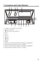
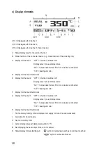
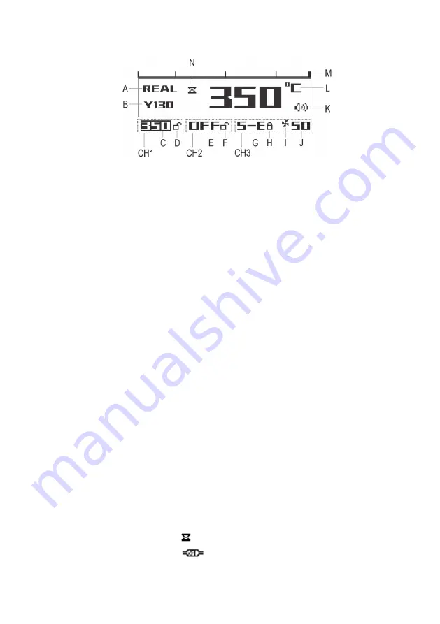
c) Display elements
CH1 = Display area for Channel 1
CH2 = Display area for Channel 2
CH3 = Display area for Channel 3 (hot air nozzle)
A Status display area for the current channel
B Model number of the connected device (e.g. model number of the soldering iron)
C Display for Channel 1: “OFF” = Channel 1 switched off
Display value = pre-set temperature
“S-E” = Temperature Sensor Error or no device is connected
“H-E” = heating unit error
D Display for Channel 1 button lock
E Display for Channel 2: “OFF” = Channel 2 switched off
Display value = pre-set temperature
“S-E” = Temperature Sensor Error or no device is connected
“H-E” = heating unit error
F Display for Channel 2 button lock
G Display for Channel 3: “OFF” = Channel 3 switched off
Display value = pre-set temperature
“S-E” = Temperature Sensor Error or no device is connected
“H-E” = heating unit error
H Display for Channel 3 button lock
I Fan function symbol (symbol is displayed: air supply for hot air nozzle is activated)
J Air volume for hot air nozzle
K Key tone on/off symbol
L Current temperature with temperature unit (°C/°F)
M Bar displaying the heat output of the current channel
N Status display for desoldering gun: “
” symbol = temperature set has not yet been reached
“
” symbol = extraction blocked

