background image

NOTE: For socket weld connections, use electric welding with a single pass. As internal parts are 
not damaged by a single welding pass, there is no need to remove them before welding.

1. The trap can be installed either horizontally or vertically, but make sure the arrow on the trap 

points in the direction of flow.

2. Before installation, be sure to remove all protective seals.
3. Before installing the trap, blow out the inlet piping to remove all dirt and oil.
4. Install the trap in the lowest part of the pipeline or equipment so the condensate flows naturally 

into the trap by gravity. The inlet pipe should be as short and have as few bends as possible.

5. Support the pipes properly within 800 mm (2.5 ft) on either side of the trap.
6. Install a bypass valve to discharge condensate, and inlet and outlet valves to isolate the trap in 

the event of trap failure or maintenance.

7. Install a check valve at the trap outlet whenever more than one trap is connected to the 

condensate collection pipeline.

8. In order to avoid excessive back pressure, make sure the discharge pipes are large enough; 

(the outlet back pressure allowance should be no more than 50% of the inlet steam pressure).

9. We recommend unions to facilitate connection and disconnection of screwed models.

4. Proper Installation

• Installation, inspection, maintenance, repairs, disassembly, adjustment 

and valve opening/closing should be carried out only by trained 
maintenance personnel. 

• Take measures to prevent people from coming into direct contact with 

product outlets.

• Install for use under conditions in which no freeze-up will occur.
• Install for use under conditions in which no water hammer will occur.

CAUTION

Check to make sure that the pipes connected to the trap have been installed properly.

1. Is the pipe diameter suitable?
2. Has sufficient space been secured for maintenance?
3. Have maintenance valves been installed at inlet and outlet? If the outlet is subject to back 

pressure, has a check valve been installed?

4. Is the inlet pipe as short as possible, with as few bends as possible, and installed so that the 

condensate will flow naturally down into the trap?

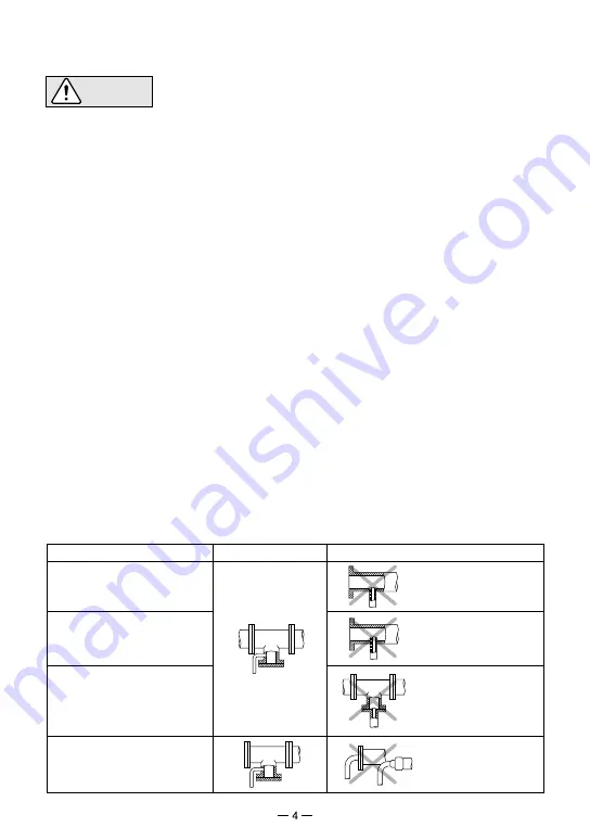
5. Has the piping work been done properly as shown in the table below?

5. Piping Arrangement

Requirement

Diameter is too
small.

Diameter is too
small and inlet
protrudes into pipe.

Rust and scale
flow into the trap
with the
condensate.

Condensate
collects in the
pipe.

Correct

Incorrect

Install a catchpot with the 
proper diameter.

Make sure the flow of 
condensate is not
obstructed.

To prevent rust and scale 
from flowing into the trap, 
connect the inlet pipe  25 - 
50 mm (1 - 2 in) above
the base of the T - pipe.

When installing on the
blind end, make sure
nothing obstructs the flow
of condensate.

Содержание PowerDyne HR150A

Страница 1: ...eserved 881 Nagasuna Noguchi Kakogawa Hyogo 675 8511 Japan Manufacturer Tel 81 0 79 422 1122 Fax 81 0 79 422 0112 THERMODYNAMIC STEAM TRAPS HR A SERIES HR150A HR260A HR80A INSTRUCTION MANUAL Keep this manual in a safe place for future reference ...

Страница 2: ...ed to indicate the degree of urgency and the scale of potential damage and danger DANGER WARNING and CAUTION The three types of cautionary items above are very important for safety be sure to observe all of them as they relate to installation use maintenance and repair Furthermore TLV accepts no responsibility for any accidents or damage occurring as a result of failure to observe these precaution...

Страница 3: ...hich may cause burns or other injury Use under conditions in which no water hammer will occur The impact of water hammer may damage the product leading to fluid discharge which may cause burns or other injury 2 Specifications To avoid malfunctions product damage accidents or serious injury install properly and DO NOT use this product outside the specification range Local regulations may restrict t...

Страница 4: ...ption No 1 2 3 4 5 6 7 8 9 10 Body Cover Module Valve Seat Disc Air Vent Ring Disc Holder Ring Module Gasket large Module Gasket small Screen Cover Bolt No 11 12 13 14 15 16 17 18 19 Nameplate not shown Cap Set Screw not shown Guide Pin Flange Cover Nut Hexagon Nut Eye Nut Spacer M R M R M Maintenance Kit R Repair Kit ...

Страница 5: ... models 4 Proper Installation Installation inspection maintenance repairs disassembly adjustment and valve opening closing should be carried out only by trained maintenance personnel Take measures to prevent people from coming into direct contact with product outlets Install for use under conditions in which no freeze up will occur Install for use under conditions in which no water hammer will occ...

Страница 6: ...m may be seen A small amount of flash steam may be visible after the discharge Blocked Discharge Impossible No condensate is discharged The trap is quiet and makes no noise The surface temperature of the trap is low Blowing Live steam continually flows from the outlet and there is a continuous metallic sound Steam Leakage Live steam is discharged through the trap outlet together with condensate ac...

Страница 7: ...without bending as it will not return to its proper shape Remove from the body Remove the gasket and clean the sealing surfaces Be careful not to bend the screen Adjust length of spacer if necessary HR150A HR260A Tighten bolts or nuts at diagonal position sequentially after having applied antiseize to the threads and threaded bolt holes It is recommended to use new bolts and nuts for the assembly ...

Страница 8: ...rect piping Trap capacity is insufficient Change to trap of suitable capacity Trap is being used below minimum operating pressure Use within pressure range Differential pressure is low Study inlet outlet pressure including rise in outlet pipe Air vent ring bimetal or disc holder ring is broken obstructing valve closure HR80A Replace air vent ring or disc holder ring HR80A Valve chattering Leakage ...

Страница 9: ...rlier of i three 3 years after delivery of Products to the first end user in the case of sealed SST Series Products for use in steam pressure service up to 650 psig ii two 2 years after delivery of Products to the first end user in the case of PowerTrap units or iii one 1 year after delivery of Products to the first end user in the case of all other Products Notwithstanding the foregoing asserting...

Страница 10: ...EREBY INCLUDING THE IMPLIED WARRANTIES OF MERCHANTABILITY AND FITNESS FOR A PARTICULAR PURPOSE CANNOT BE EXCLUDED SUCH DAMAGES ARE EXPRESSLY LIMITED IN AMOUNT TO THE PURCHASE PRICE OF THE DEFECTIVE PRODUCT THIS EXCLUSION OF CONSEQUENTIAL AND INCIDENTAL DAMAGES AND THE PROVISION OF THIS WARRANTY LIMITING REMEDIES HEREUNDER TO REPLACEMENT ARE INDEPENDENT PROVISIONS AND ANY DETERMINATION THAT THE LIM...

Страница 11: ...10 ...

Страница 12: ...Printed on recycled paper Tel 81 0 79 422 1122 Fax 81 0 79 422 0112 Rev 10 2021 M PAC 65339 a 881 Nagasuna Noguchi Kakogawa Hyogo 675 8511 Japan Manufacturer ...

Отзывы: