44
44
NC20 - Manual - 01 - 2015
FUNCTION CHARACTERISTICS
Communication interfaces
Several communication ports are provided:
RS232 port on the front side of the NC20 device for local communication (ThySetter).
RS485 port on the rear side of the NC20 device for bus communication.
Ethernet port on the rear side of the NC20 device for bus communication.
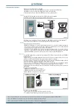
RS232
A simple DIN to RJ adapter can be used; the L10041 cable can be supplied.
The RS232 port has high priority compared with the Ethernet port.
If RS232 port is not available on Personal Computer, an USB-RS232 converter must be employed.
[1]
The serial port is the simplest access for setting by means the ThySetter software.
RS485
Several protocol are implemented
[2]
:
ModBus RTU. Modbus is a serial communications protocol. It is a de facto standard communica-
tions protocol in industry, and is now the most commonly available means of connecting industrial
electronic devices also inside electric utilities and substation.
IEC 60870-5. The IEC 60870-5 suite of protocol is used for communications from master station to
substation, as well within the substation; the IEC 60870-5-103 (Protection equipment) is available
together the Modbus protocol on some version of Pro-n devices (code NCxx#xxxxC x).
Ethernet
It is provided (optionally) a communication board useful for Ethernet communication with ModBus
TCP/IP protocol.
[3]
Modbus/TCP basically embeds a Modbus frame into a TCP frame in a simple manner. This is a con-
nection-oriented transaction which means every query expects a response.
This query/response technique fi ts well with the master/slave nature of ModBus, adding to the de-
terministic advantage that Switched Ethernet offers industrial users.
In the same way as the RS485 base Modbus, every device is identifi ed by a personal address and the
communication goes in “client-server” mode with answering request from the recipient.
The protective relay can be directly connect to the Ethernet network (no gateway, protocol converter
are needed).
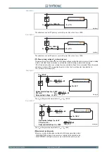
Two port can be implemented:
100BASE-TX with RJ45 connector (copper).
100BASE-FX with FX connector (optical fi ber)
[2]
For both modules no hw preset are required.
Two LEDs are on board (RJ45):
LINK - (green): The LED lights up if the connection is active.
TX - (yellow): The LED lights up when data transmission is active.
Note 1 After installation, the same communication port must be selected to defi ne the Thysetter parameters (typically COM4, COM5,...).
Note 2 The RS485 port is not implemented on the Pro-N devices endowed with Ethernet FX port
Note 3 Information about the ModBus map may be fi nd inside the “Remote programming manual”
•
•
•
•
•
•
•
•
•
serial-sch.ai
L10041
TXD
RXD
DTR
GND
4
3
1
2
1
2
3
4
6
7
8
9
5
Female connector
RJ10 Connector
Pin1
serial-sch.ai
L10041
TXD
RXD
DTR
GND
4
3
1
2
1
2
3
4
6
7
8
9
5
Female connector
RJ10 Connector
Pin1
ethernet-sch.ai
RX
FX Ethernet (no RS485 port)
TX
1 TX+
2 TX-
3 RX+
4
5
6 RX-
7
8
RJ45 ERS485 ports
RS485
F1
F2
F3
F4
F5
A+
B-
ethernet-sch.ai
RX
FX Ethernet (no RS485 port)
TX
1 TX+
2 TX-
3 RX+
4
5
6 RX-
7
8
RJ45 ERS485 ports
RS485
F1
F2
F3
F4
F5
A+
B-

