

133
NC20 - Manual - 01 - 2015
MEASURES, LOGIC STATES AND COUNTERS
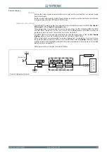
Event recording - SER
Recording is triggered by:
Relay switching (OFF-ON or ON-OFF).
External trigger (binary input).
Setting change.
Three hundred events are recorded into a circular FIFO (First In, First Out) buffer.
[1]
Following information are stored in every record:
Event counter
[2]
Date and time
Event cause (binary input/output relay/setting changes)
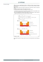
Oscillography - DFR
Upon programmable trigger, the fault records are recorded in COMTRADE format; the sampled mea-
sures (24 sample per cycle) are stored in a circular shift memory buffer.
The fault record are self-triggered; they are stored in sequential order up the allocated memory is
used up after which the oldest memory is overwritten.
An operating procedure example for the digital fault recording is illustrated inside the ThySetter
section.
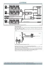
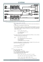
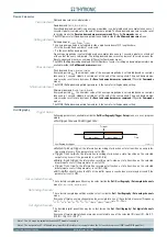
Trigger setup
The information storage starts when a state transition on the selected signal occurs. (protective ele-
ment start and/or trip, output relay and/or binary input switching).
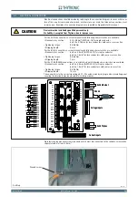
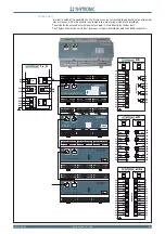
Pre-trigger and post-trigger time
Alarm: when the 80% of the buffer space is reached an alarm may be issued. The system being of
linear type, the records are back-to-back recorded to the end of available memory; the alarm out-
put is a warning in order that the user may download data
[3]
to clear memory for new records.
Following parameters are user-programmable:
Sample channels
Instantaneous value for phase currents
i
L1
,
i
L2
,
i
L3
Instantaneous value for unbalance neutral current
i
N
Instantaneous value for input voltages
u
L1
,
u
L2
,
u
L3
Analog channels
RMS value for phase currents
I
L1RMS
,
I
L2RMS
,
I
L3RMS
Fundamental component for phase currents
I
L1
,
I
L2
,
I
L3
Fundamental component for input voltages
U
L1
,
U
L2
,
U
L3
Fundamental component for calculated residual current
I
EC
Fundamental component for unbalance neutral current
I
N
Displacement angle of unbalance neutral current with respect to
I
L1
phase current
Phi
N
Fundamental component for unbalance compensated current
I
NC
Displacement angle of unbalance compensated current with respect to
I
L1
phase current
Phi
NC
Unbalance phase current
I
2
Digital channels
Binary inputs
Output relays
COMTRADE
Records are recorded in COMTRADE format; (Common Format for Transient Data); This is a standard
for the data exchange for various types of tests or simulation datas, etc, for power system applica-
tions.
The measurements are recorded in ASCII or BINARY format. COMTRADE fi les always come by
pairs:
The “.CFG”-fi le describing the confi guration: number of analog and digital channels, sampling rate,
scale factors, etc.
The “.DAT”-fi le containing the data
The COMTRADE is part of IEC 60255-24 standard.
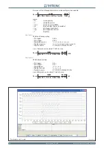
The recording can be analyzed by mean of ThySetter sw or any other standard compliant viewer.
The record quantity is depending on settings of following parameters:
Pre-trigger and post-trigger times
Number of allocated channels.
Note 1 Event 0 is the newest event, while the Event 299 is the oldest event
Note 2 Counter is updated at any new record; it may be cleared by means ThySetter
Note 3 Data are stored into non-volatile memory; they are retained once power is turned off.
•
•
•
•
•
•
•
•
•
•
•
•
•
•
•
•
•
•
•
•
•
•
•
•
•
•
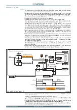
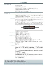
trigger.ai
Oscillographic recorder - trigger
Trigger
Time
pre-trigger
post-trigger
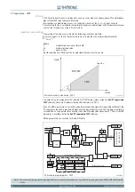
trigger.ai
Oscillographic recorder - trigger
Trigger
Time
pre-trigger
post-trigger


