


106
106
NC20 - Manual - 01 - 2015
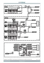
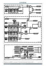
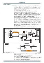
FUNCTION CHARACTERISTICS
Overvoltage - 59
Preface
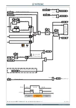
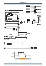
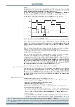
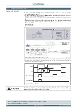
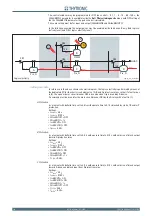
Two operation thresholds, independently adjustable (
U
>,
U
>>) with adjustable delay (
t
U
>,
t
U
>>).
The fi rst one may be programmed with defi nite or inverse time, while the second threshold operates
with defi nite time characteristic.
Each threshold may be separately enabled or disabled.
The fi rst threshold trip (
U
>) may be inhibited by start of the second threshold (
U
>>).
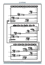
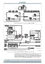
Operation and settings
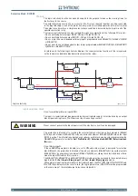
The fundamental frequency of the input voltages (
U
L1
,
U
L2
,
U
L3
) are utilized.
Each of three voltages is compared with the setting values (
U
>,
U
>>). The start and trip logic may
be selected
OR
or
AND
.
With
OR
selection, a start is issued when at least one of the three voltages overcomes the adjust-
able threshold (START); after expiry of the associated operate time (
t
U
>,
t
U
>>) a trip command is
issued; if instead the voltages drop below the threshold, the element is restored.
With
AND
selection, a start is issued when all the three voltages overcomes the adjustable thresh-
old; after expiry of the associated operate time (
t
U
>,
t
U
>>) a trip command is issued; if instead the
voltage drops below the threshold, the element is restored.
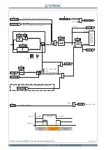
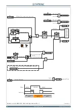
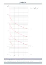
The fi rst threshold (
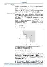
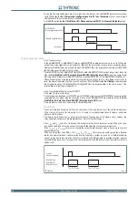
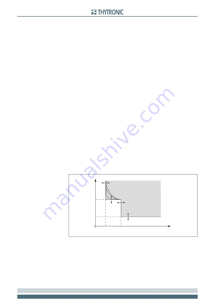
U
>) may be programmed with defi nite or inverse time according the following
characteristic curve:
t
=0.5
t
U
>
inv
/ [(
U
/
U
>
inv
) - 1]
Where:
t
: operate
time
U
: relay
input
voltage
U
>
inv
: threshold
setting
t
U>inv
: operate
time
setting
For the inverse time characteristic, following data applies:
The operate time setting is referred to an input voltage equal to 1.5 of the pickup value.
Asymptotic reference value (minimum pickup value): 1.1
U
>
inv
Minimum operate time:
0.1 s
Range where the equation is valid: 1.1 ≤
U
/
U
>
inv
≤ 4
If
U
>
inv
pickup ≥ 0.5
U
n
, the upper limit is 2
U
n
.
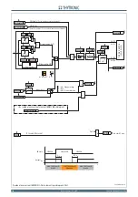
The fi rst overvoltage element can be programmed with defi nite or inverse time characteristic by
setting the
U>Curve
parameter (
DEFINITE, INVERSE
) available inside the
Set \ Profi le A(or B) \
Overvoltage-59 \
U
> Element \ Setpoints
menu.
Each element can be enabled or disabled by setting
ON
or
OFF
the
U> Enable
parameter inside
the
Set \ Profi le A(or B) \ Overvoltage-59 \
U
> Element \ Setpoints
menu and/or the
State
parameter
inside the
Set \ Profi le A(or B) \ Overvoltage-59 \
U
>> Element \ Defi nite time
.
The operating logic (AND or OR) is adjustable inside the
Set \ Profi le A(or B) \ Overvoltage-59 \ Com-
mon confi guration
menu by means the
Logic59
parameter
;
the allowed settings are
OR
(at least
one voltage greater than threshold) or
And
(all three voltage must be greater than threshold).
The fi rst threshold trip (
U
>) may be inhibited by start of the second threshold (
U
>>) by setting
ON
the U> Disabling by U>> start (
U>disbyU>>
) parameter available inside the
Set \ Profi le A(or B) \
Overvoltage-59 \ U>> Element \ Setpoints
menu.
Both overvoltage elements can produce the Breaker Failure output if the
U> BF
and
U>>BF
pa-
rameters are set to
ON.
The parameters are available inside the
Set \ Profi le A(or B) \ Overvoltage - 59 \
U> Element
(
U>>
Element) \ Setpoints
menus.
[1]
Note 1 The common settings concerning the Breaker failure protection are adjustable inside the
Breaker Failure - BF
menu.
•
•
•
•
•
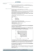
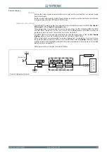
t-int-F59.ai
U
U
>>
t
U
>
t
U
>>
U
>
t
TRIP
General operation time characteristic for the overvoltage elements - 59


