


115
NC20 - Manual - 01 - 2015
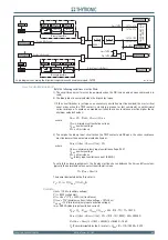
FUNCTION CHARACTERISTICS
Operation
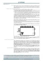
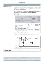
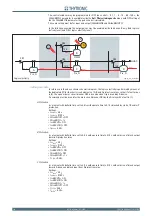
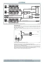
For any protective element, three main conditions can arise:
Start = OFF: the element is at rest (no trip) regardless of the input/output blocks.
Start = ON: the element trips if no selective block input becomes active during the operate time.
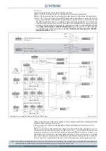
Start = ON: if the selective block input (BLIN1 and/or binary input) becomes active, the element
goes in selective block state wherein the operate timer is forced to reset, so the element cannot
trip. After an adjustable time
t
B-Iph
(common for phase protection elements) or
t
B-IE
(common for
earth protection elements), the selective block input is disregarded and the operate timer can
start again. Information about
t
B-Iph
and or
t
B-IE
expired is available for reading (
tB timeout
data
inside
Read \ Selective block - BLOCK2 \ Block2 input
menu) and can drive an output relay and
or a LED (
tB-K
and or
tB-K
parameters inside
Set \ Profi le A(or B) \ Selective block - BLOCK2 \
Selective block IN
submenu).
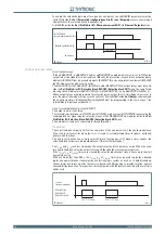
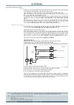
With a setting other than 0.00 s, the
t
B-Iph
and
t
B-IE
timers may be used to have a backup protection
available against pilot wire short circuit.
[1]
The
t
B-Iph
and/or
t
B-IE
timers must be adjusted according the following rule (example for
t
B-Iph
):
t
B-Iph
=
t
F
v
+
ε
t
+
ε
s
where
t
F
v
is the value of block output timer related to the downstream relay (example
t
F-Iph
),
ε
t
is a
chronometric selectivity margin to apply in comparison to the
t
B-Iph
time related to the downstream
relay (does not take into account if such margin has been considered for the
t
F-Iph
setting),
ε
s
is a
safety margin. The chronometric selectivity applied among the
t
B-x
times of the relays in accelerated
logic system allows to avoid more the contemporary circuit breaker opening after the clearing of a
fault in a line of concomitant plant to the short-circuit of the pilot wires concerning the same line.
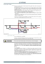
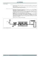
Note 1 In the absence of suitable provisions, a short circuit on a pilot wire causes the block of the receiving relay, so a possible fault (contemporary or
following) inside the protected zone, cannot be cleared that being the case the protective relay blocked.
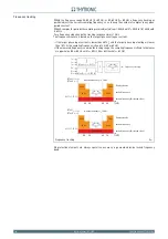
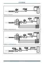
A)
B)
C)
Binary input INx
T
0
Logic
INx
t
ON
INx
t
ON
INx
t
OFF
T
0
n.o.
n.c.
INx
t
OFF
Binary input INx
T
0
Logic
INx
t
ON
INx
t
ON
INx
t
OFF
T
0
n.o.
n.c.
INx
t
OFF
Binary input INx
T
0
Logic
INx
t
ON
INx
t
ON
INx
t
OFF
T
0
n.o.
n.c.
INx
t
OFF
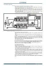
Block2 IPh
Block2 IPh/IE
ModeBLIN1
PulseBLIN1
T
0
Pilot wire
Diagnostic
Pulse BLIN1
Block2-in-diagram.ai
≥
1
≥
1
≥
1
≥
1
BLK2IN xx
&
&
&
Pilot wire input
No pulses
Permanently “ON”
xxBLK2IN
BLK2IN-Iph
Start
xx
Trip
xx
BLK2IN I>
&
&
Block2 input enable (I> element)
(IN>, IN>>, DthAL1, DthAL2, Dth>, I>, I>>, I>>>, IE>, IE>>, IE>>>, elements)
Block2 input enable
(ON
≡
Enable)
&
I>BLK2IN
Start
I>
Trip
I>
Iph Block2
IE Block2
BLK2IN-IE
tB timeout
FROM EARTH FAULT PROTECTIONS
FROM ANY PROTECTIONS
FROM PHASE PROTECTIONS
OFF
ON IPh
ON IPh/IE
ON IE
BLIN1
Block2 IE
Breaked BLIN1
TRIP
P
ING
M
A
TRIX
(LED
+R
EL
A
Y
S
)
≥
1
≥
1
Shorted BLIN1
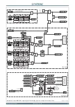
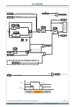
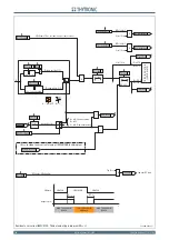
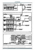
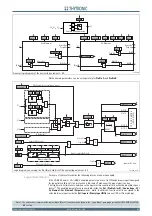
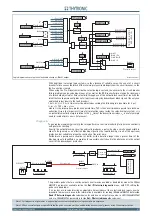
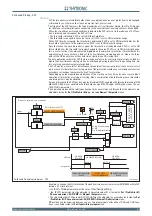
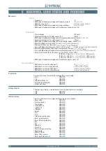
Logic diagram concerning the selective block intput - Block2 input
T
0
t
B-Iph
t
B-Iph
t
B-IE
T
0
t
B-IE


