


26
26
NC20 - Manual - 01 - 2015
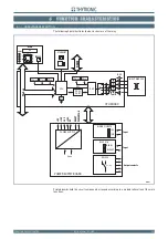
FUNCTION CHARACTERISTICS
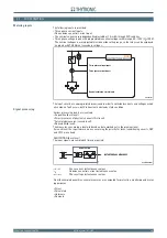
Power supply board
All the components necessary for conversion and stabilization functions are present.
Two versions are envisaged suited to the input ranges 24...48 V and 115...230 V.
The circuit provides stabilized voltages of +10 V and -10 V, required for the analogue measurement,
+24V for relays and +5 V for supplying the digital circuits.
The circuit board additionally comprises:
INPUT CIRCUITS:
Two binary input circuits,
One block input circuit (BLIN1).
The logical input circuits and the block circuits include photo-couplers which provide for galvanic
separation.
OUTPUT CIRCUITS:
One block output circuit (BLOUT 1),
Six output relays (k1...K6).
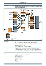
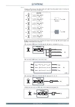
CPU board
This circuit board contains all the circuits necessary for performing the analogue and digital pro-
cessing of the signals.
Analog processing
The following are envisaged:
Anti aliasing fi lter circuits,
Amplifi er circuits for conditioning the input signals,
Reference voltage adjustment circuits for the measurement A/D converter.
The Pro-n relays use a DSP processor operating at 40 MHz; it performs all the processing on the
analogue signals and furthermore coordinates management of the TX-RX signals to the CPU.
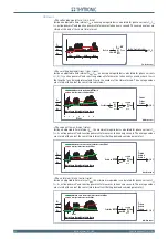
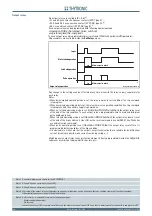
The input currents are sampled at a frequency of 24 samples per period by means of a dual conver-
sion system which allows the attainment of information pertaining to polarity and amplitude with high
resolution. The measurement criterion allows precise measurement of even those signals having a
unidirectional component, such as transient currents with overlapping exponential, which typically
appear during faults.
The circuit board also houses the output relays with the corresponding command and control cir-
cuits, communication circuits, buttons, LCD display, LEDs and the key switch.
CPU
A 32 bit CPU is provided.
The following are envisaged:
Real Time Clock circuits with oscillator and super capacitor,
RS232 communication port,
RS485 communication port,
Thybus communication circuits for external modules and MMI board,
Network communication circuits (optional Ethernet).
Memories:
SRam: high speed static memory, used for data and cache,
Flash memory: used for fw storage and upgrade,
EEprom memory: used for calibration data storage,
Dual port Ram for data transfer between CPU and DSP.
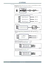
Input board
Three CTs committed for phase currents acquisition,
One CT committed for neutral current acquisition.
The input circuits are suitable for 1 A or 5 A external CTs.
[1]
Three VTs committed for phase voltages acquisition.
MMI (keyboard, LED and display)
The MMI module (Man Machine Interface) includes:
An eight keys 8 keyboard,
a backlight LCD display,
Eight signalling LEDs,
The removable plug allows separation of the MMI module for free access to the CPU board when
DIP-switch setting is required.
Note 1 The phase and residual nominal currents must be adjusted by means dip-switch.
•
•
•
•
•
•
•
•
•
•
•
•
•
•
•
•
•
•
•
•
•
•


