background image


pg. 19

Before connecting the central heating cooker to the flue outlet it is advisable to check the flue outlet draft. This operation can be carried out

using a draft gauge: the vacuum must measure 1.5 - 2 mm water gauge.

We recommend having an expert technician control the flue outlet at least once a year.

Poor draft causes poor combustion which results in a reduced power.

It is important to be aware of the fact that in terms of correct functioning and safe usage the flue outlet is just as important as the central heating

cooker. The smoke pipes must be connected to the flue outlet in the same room in which the heater is installed or in an adjacent room and must

satisfy the following requirements:

 be airtight and be capable of resisting normal mechanical stress, heat and the action of the combustion products and condensate over long

periods of time. The temperature of the gases, at any point in the channel, must be above dew point;

 the joints must be sealed tight; if materials are used for this purpose they must be capable of resisting high temperatures;

 be in full view, easily accessed for removal and installed in such a way as to be capable of resisting normal thermal expansion;

 be installed in such a way that end of the tube with the smaller diameter faces the smoke vent and the end with the larger diameter faces the

flue outlet

 have a horizontal run with a minimum upward slope of 3-5% (3-5 cm for each metre of tube ). The horizontal-sloped part must not be longer than

1/4 of the height of the flue outlet, and in any case must have a maximum length of 2.5m;

have no more than 3 changes of direction, including the flue outlet connector, and with internal corners that are a minimum of 90°. The changes

of direction must only be made with curved elements;

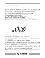
have (as described in the figure above) the axis of the female end perpendicular to the opposite wall of the flue outlet, without protruding into the

pipe;

 Have, along its entire length, a section which is equal to or greater than that of the appliance’s exhaust tube fitting;

 Have no shut off devices ( damper): if devices such as these are already installed they must be eliminated.

The previous chapter does not replace UNI 7129/92 and UNI 10683/98 to which it makes reference. The qualified installer

must in any case be fully aware of this standard and its amending versions.


       YES                        NO

7 . 4

7 . 4

7 . 4

7 . 4

7 . 4

CONNECTION 

CONNECTION 

CONNECTION 

CONNECTION 

CONNECTION  T

T

T

T

TO 

O THE FL

THE FL

THE FL

THE FL

THE FLUE OUTLET

UE OUTLET

UE OUTLET

UE OUTLET

UE OUTLET

7 . 3

7 . 3

7 . 3

7 . 3

7 . 3

VENTILA

VENTILA

VENTILA

VENTILA

VENTILATION OF 

TION OF 

TION OF 

TION OF 

TION OF  THE R

THE R

THE R

THE R

THE ROOMS

OOMS

OOMS

OOMS

OOMS

It is essential for the room in which the appliance is installed to be well-ventilated, also to guarantee secondary air for combustion in the central

heating cooker.

The natural air flow occurs directly through permanent apertures to the outside made in the walls of the room, or by means of single or multiple

ventilation ducting.

The ventilating air must come from outside and if possible, away from sources of pollution. Indirect ventilation is also allowed by taking in air from

rooms adjacent the one where the heater is installed taking into account all the warnings and limitations specified below.

•The apertures in the walls must comply with the following requirements:

- -have an unobstructed section of at least 6cm² for each Kw of installed thermal power, with a minimum limit of 100cm²;

- be made in such a way that the vent openings, both on the inside and outside of the wall, cannot be obstructed;

- be protected with grills or similar systems in order not to reduce the section described above;

- be situated at floor-level.

The air flow can also be obtained from an adjacent room as long as:

- the adjacent room is equipped with direct ventilation in compliance with the points described above;

- in the room to be ventilated the installed appliances are only connected to one flue outlet;

- the adjacent room is not used as a bedroom or a common area of the building;

- the adjacent room is not a room with a fire hazard, such as storage sheds, garages, combustible material store rooms, etc...;

- the adjacent room does not become a vacuum compared to the room to be ventilated due to an opposite draught effect;

- the air flow from the adjacent room to the room to be ventilated is unobstructed through the permanent apertures having an overall net section

of no less than that indicated above. These apertures can be obtained by enlarging the space between the door and the floor.


Содержание BOSKY series

Страница 1: ...36011 Arsiero vi ITALY Via Grumolo 4 tel 0445 741310 fax 0445741657 www thermorossi com USE AND MAINTENANCE GUIDE CENTRAL HEATING COOKER 25 30 F25 F30 60 65 650 90 95 920 ...

Страница 2: ...ntral heating cookers 5 4 Grate positions in the central heating cookers 5 5 How to use the oven in central heating cookers F25 F30 60 90 920 5 6 The fold away towel rack only for 25 30 F25 F30 6 CLEANING AND MAINTENANCE 6 1 General cleaning 6 2 Ash 6 3 How to clean the radiant plate 6 4 How to replace the oven light bulb 6 5 Recommendations 7 SMOKE EXHAUST PIPE 7 1 General 7 2 Essential requireme...

Страница 3: ... heating system The appliances will not function correctly if the instructions are not observed correctly 1 3 1 3 1 3 1 3 1 3 ST ST ST ST STAND AND AND AND ANDARDS ARDS ARDS ARDS ARDS AND RECOMMEND AND RECOMMEND AND RECOMMEND AND RECOMMEND AND RECOMMENDA A A A ATIONS TIONS TIONS TIONS TIONS Normative references national and international standards used as reference guides for the design industrial...

Страница 4: ... 26 R itorn o 1 1 4 m od B O S K Y 25 3 0 A n data1 1 4 707 669 3 1 0 71 75 71 4 785 S caricoterm ico1 2 63 6 482 A ttacc oc am in o 1 5 0 O 1 05 5 869 1 26 4 m o d B O S K Y F 25 F 3 0 4 82 R ito rn o1 1 4 707 3 1 0 71 75 669 71 4 785 S caric ote rm ic o1 2 A n d ata1 1 4 Key Flue outlet connection Delivery Return Thermal discharge Legenda Attacco Camino Andata Ritorno Scarico termico ...

Страница 5: ...Delivery Return Thermal discharge Model Rear view Sideview View from above Technical Characteristics Legenda Attacco Camino Andata Ritorno Scarico termico Modello Vista posteriore Vista laterale Vista dall alto Caratteristiche tecniche ...

Страница 6: ... i o B 5 2 0 2 5 2 m m y e n m i h c y b d e r i u q e r c a V n m u l o c r e t a w 2 2 2 g K h g i e w l a t o T 5 9 2 0 6 2 5 7 2 A T A D L A C I N H C E T A T A D L A C I N H C E T A T A D L A C I N H C E T A T A D L A C I N H C E T A T A D L A C I N H C E T 0 5 6 Y K S O B 0 5 6 Y K S O B 0 5 6 Y K S O B 0 5 6 Y K S O B 0 5 6 Y K S O B 5 6 Y K S O B 5 6 Y K S O B 5 6 Y K S O B 5 6 Y K S O B 5...

Страница 7: ...L A C I N H C E T A T A D L A C I N H C E T A T A D L A C I N H C E T 5 2 F Y K S O B 5 2 F Y K S O B 5 2 F Y K S O B 5 2 F Y K S O B 5 2 F Y K S O B 0 3 F Y K S O B 0 3 F Y K S O B 0 3 F Y K S O B 0 3 F Y K S O B 0 3 F Y K S O B 5 2 Y K S O B 5 2 Y K S O B 5 2 Y K S O B 5 2 Y K S O B 5 2 Y K S O B 0 3 Y K S O B 0 3 Y K S O B 0 3 Y K S O B 0 3 Y K S O B 0 3 Y K S O B W k y t i c a p a c x o b e r ...

Страница 8: ...TIONAL ONL AL ONL AL ONL AL ONL AL ONLY FOR 25 30 F25 F30 Y FOR 25 30 F25 F30 Y FOR 25 30 F25 F30 Y FOR 25 30 F25 F30 Y FOR 25 30 F25 F30 A vital aspect to consider is that the flooring of the room in which the central heating cooker is installed must be capable of bearing the weight of the central heating cooker CAUTION The room in which the central heating cooker is installed must be adequately ...

Страница 9: ... CAUTION IT IS MANDATORY TO EARTH THE CENTRAL HEATING COOKER AS ILLUSTRATED IN THE ABOVE DIAGRAM IF THIS INSTRUCTION IS NOT OBSERVED SERIOUS DAMAGE WHICH IS NOT COVERED BY WARRANTY WILL RESULT TO THE BODY OF THE CENTRAL HEATING COOKER HAVE AN ELECTRICAIN CHECK THE EARTHING THERE MUST BE NO ELECTRIC POTENTIAL VOLTS BETWEEN THE EARTH OF THE CENTRAL HEATING COOKER EARTHAND THE ACTUAL EARTH OF THE PLA...

Страница 10: ...ng pump anticondensation thermostat anticondensation thermostat PUMP CONNECTION Connect the pump to terminals no 4 and 5 and make a bridge connection for terminals no 5 and 6 CAUTION IT IS MANDATORY TO EARTH THE CENTRAL HEATING COOKER AS ILLUSTRATED IN THE ABOVE DIAGRAM IF THIS INSTRUCTION IS NOT OBSERVED SERIOUS DAMAGE WHICH IS NOT COVERED BY WARRANTY WILL RESULT TO THE BODY OF THE CENTRAL HEATIN...

Страница 11: ...ing cooker We recommend you earth the central heating cooker and check the efficiency of the earthing of the electrical system to which the central heating cooker is connected A A n d ataim p ian toris cald am e n to R R ito rn oim p ian toris c ald am e n to E T u b od i s ic u re zzach ev ad allac ald aia al v as od i e s p an s io n eap e rto S S c aricod e llac ald aia P C P o m p ac irc o laz...

Страница 12: ...OF CASING FOR BOSKY 25 30 F25 F30 TION OF CASING FOR BOSKY 25 30 F25 F30 TION OF CASING FOR BOSKY 25 30 F25 F30 After positioning the central heating cooker connecting the electrical system and the hydraulic system only if using the rear delivery and return outlets see para 4 2 4 3 4 4 4 5 4 6 4 7 4 8 4 9 proceed with the installation of the casing as illustrated in the images below Firstly mount ...

Страница 13: ...N OF MAIN CONTROLS AND COMPONENTS DESCRIPTION OF MAIN CONTROLS AND COMPONENTS DESCRIPTION OF MAIN CONTROLS AND COMPONENTS DESCRIPTION OF MAIN CONTROLS AND COMPONENTS 5 1 1 5 1 1 5 1 1 5 1 1 5 1 1 DESCRIPTION OF MAIN CONTR DESCRIPTION OF MAIN CONTR DESCRIPTION OF MAIN CONTR DESCRIPTION OF MAIN CONTR DESCRIPTION OF MAIN CONTROLS OLS OLS OLS OLS AND COMPONENTS OF CENTRAL HEA AND COMPONENTS OF CENTRAL...

Страница 14: ...l heating cooker to your heating or cooking needs In models 60 65 90 95 650 920 a secondary air slide is located on the loading door for the ingress of secondary air The heating pump starts up as soon as the anticondensation thermostat calibrated at 60 C gives the start signal to the plant circulating pump The pump switch only for models 60 65 650 90 95 920 must be positioned on 1 ON The maximum t...

Страница 15: ...F30 F30 F30 F30 Central heating cookers models 25 30 F25 F30 are fitted with 2 practical foldaway racks for hanging your washing on to dry To extend them simply pull out as indicated in the figure on the right O N 5 4 5 4 5 4 5 4 5 4 GRA GRA GRA GRA GRATE POSITIONS IN TE POSITIONS IN TE POSITIONS IN TE POSITIONS IN TE POSITIONS IN THE CENTRAL HEA THE CENTRAL HEA THE CENTRAL HEA THE CENTRAL HEA THE...

Страница 16: ...nect the central heating cooker from the electrical power outlet Your central heating cooker does not require any special maintenance simply adhere to the simple and basic but regular controls and general cleaning This will guarantee regular operation and optimal output at all times As for all machines that run on solid fuel the main enemy is undoubtedly the dirt generated by ash condensation poor...

Страница 17: ...is installed be fitted at the top with a cap that fulfils definite requirements must not be installed in inhabited locations as the flue outlet is always slightly more pressurised that its surroundings If you use a large pre existing chimney you can adapt it by installing a stainless steel chimney liner then filling in the spaces between the liner and the chimney with insulating material 7 1 7 1 7...

Страница 18: ...ed on top of a flue outlet for the purpose of facilitating dispersion of the combustion products it must satisfy the following requirements have a useful exhaust section that is at least double the section of the flue outlet on which it is inserted have a shape that prevents the entry of snow or rain into the flue outlet be built in such a way that venting of the combustion products is guaranteed ...

Страница 19: ...not replace UNI 7129 92 and UNI 10683 98 to which it makes reference The qualified installer must in any case be fully aware of this standard and its amending versions YES NO 7 4 7 4 7 4 7 4 7 4 CONNECTION CONNECTION CONNECTION CONNECTION CONNECTION T T T T TO O O O O THE FL THE FL THE FL THE FL THE FLUE OUTLET UE OUTLET UE OUTLET UE OUTLET UE OUTLET 7 3 7 3 7 3 7 3 7 3 VENTILA VENTILA VENTILA VEN...

Страница 20: ... pieces Poor draft See causes remedies Poor draft below Insufficient air in the room Create an adequate opening for air inlet see PARA 7 3 Oxidised cook top Poor maintaince of the cook top Clean and maintain cook top as described in para 6 3 Impossible to operate at night the fuel burns too quickly Uncontrolled combustion Draft too strong Reduce the draft by installing a register in the chimney Po...

Страница 21: ...6001 1 548 7001 1 799 B IA N C A 7001 1 859 B E IG E 7001 1 860 R O S S O 7001 1 857 C A N N AF U C IL E 7001 1 858 M A R R O NF U M E 7001 1 840 B IA N C A 7001 1 881 C A N N AF U C IL E 7001 1 882 M A R R O NF U M E 7001 1 883 B E IG E 7001 1 884 R O S S O 9 9 9 9 9 SP SP SP SP SPARE P ARE P ARE P ARE P ARE PAR AR AR AR ARTS TS TS TS TS 9 1 9 1 9 1 9 1 9 1 SP SP SP SP SPARE P ARE P ARE P ARE P A...

Страница 22: ... 60004241 60004228 6001 1 63 3 60004241 60004276 8001 1 63 1 G U A R N IZ IO N E 6001 1 5 5 7 6001 1 5 1 2 7001 2201 8001 1 61 7 G U A R N IZ 6001 03 3 5 6001 01 91F IN O1 2 2007 6001 1 5 1 9 3 3 6x3 3 8x4 7001 1 687 7001 1 692 80006480 600043 20 600043 20 60004286 600091 61 7001 1 925 600071 02 7001 1 688 6001 1 5 21 6001 1 722C E R C H I ING H IS A 6001 1 5 71 S C A M B IA T O R EA L E T T A T O...

Страница 23: ...6001 1 5 68 7001 1 792 7001 23 79 7001 1 789 D A L1 8 04 06 7001 1 792 8001 1 63 2 7001 1 792 7001 1 789 70 01 1 962B E IG E 70 01 1 964R O S S O 70 01 1 961C A N N AF U C IL E 70 01 1 960 B IA N C O 70 01 1 963M A R R O NF U M E 80 01 1 61 4 8001 1 61 3 8001 1 61 5 60 01 1 5 66 6001 1 5 49 6001 1 5 49 6001 1 5 69 6001 1 5 83 6001 1 5 69 6001 1 5 48 6001 01 70 6001 1 5 4 9 70 01 1 865C A N N AF U ...

Страница 24: ...629 6001 1 5 1 2 7001 1 689 600091 61 60004286 6001 1 620 600071 02 7001 1 692 80006480 600043 20 600043 20 6001 1 5 46 7001 1 785 7001 1 83 4 6001 1 5 60 7001 1 83 5 6001 0762 6001 1 5 5 9 6001 0762 60004228 6001 1 63 3 60004246 60004246 60004241 60004276 8001 1 63 1 8001 1 626 7001 2202 8001 1 625 7001 2200 7001 1 663 7001 21 99 6001 1 5 5 6 7001 1 81 0 7001 1 81 1 6001 1 5 71 S C A M B IA T O R...

Страница 25: ...0 P TS FOR BOSKY 60 90 PAR AR AR AR ART 1 T 1 T 1 T 1 T 1 Key Cast iron rings BLACK White Glass Dark brown Grey Grey Greyhandle Dark brown handle For GreyDisk Enamelled Disk From April 2005 ToApril 2005 Legenda Cerchi in ghisa Nero Bianco Vetr Testa moro Testa grigia grigia Maniglia grigia Maniglia t moro Per Disco Grigio Disco Smaltato Da Aprile 2005 Fino Aprile 2005 ...

Страница 26: ...FOR BOSKY 65 95 P TS FOR BOSKY 65 95 P TS FOR BOSKY 65 95 P TS FOR BOSKY 65 95 PAR AR AR AR ART 1 T 1 T 1 T 1 T 1 Key GreyDisk Enamelled Disk Satin finish Grey Dark brown Grey Black White Cast iron ring set Legenda Disco Grigio Disco Smalto Satinato Grigio Testa moro Testa grigia Nero Bianco Serie cerchi in ghisa ...

Страница 27: ... P ARE P ARE PAR AR AR AR ARTS FOR BOSKY 650 P TS FOR BOSKY 650 P TS FOR BOSKY 650 P TS FOR BOSKY 650 P TS FOR BOSKY 650 PAR AR AR AR ART 1 T 1 T 1 T 1 T 1 Key Water Beige Disk Side handle kit Vin P S Legenda Acqua Beige Disco Kit maniglie laterali Vin P S ...

Страница 28: ...920 P TS FOR BOSKY 920 P TS FOR BOSKY 920 P TS FOR BOSKY 920 P TS FOR BOSKY 920 PAR AR AR AR ART 1 T 1 T 1 T 1 T 1 Key S P Wine Water Beige ToApril 2005 From April 2005 Fixed hinge element Side handle kit Legenda P S Vin Acqua Beige Fino ad aprile 2005 Da aprile 2005 Portarullino Kit maniglie laterali ...

Страница 29: ...R AR AR AR ARTS FOR BOSKY 60 65 90 95 650 920 P TS FOR BOSKY 60 65 90 95 650 920 P TS FOR BOSKY 60 65 90 95 650 920 P TS FOR BOSKY 60 65 90 95 650 920 P TS FOR BOSKY 60 65 90 95 650 920 PAR AR AR AR ART 2 T 2 T 2 T 2 T 2 Key S P Vin Water Beige Legenda P S Vin Acqua Beige ...

Страница 30: ... TS FOR BOSKY 60 90 ELECTRIC PANEL ANEL ANEL ANEL ANEL WITH ELECTRIC O WITH ELECTRIC O WITH ELECTRIC O WITH ELECTRIC O WITH ELECTRIC OVEN VEN VEN VEN VEN 9 10 9 10 9 10 9 10 9 10 SP SP SP SP SPARE P ARE P ARE P ARE P ARE PAR AR AR AR ARTS FOR BOSKY 60 90 ELECTRIC P TS FOR BOSKY 60 90 ELECTRIC P TS FOR BOSKY 60 90 ELECTRIC P TS FOR BOSKY 60 90 ELECTRIC P TS FOR BOSKY 60 90 ELECTRIC PANEL ANEL ANEL ...

Страница 31: ...BOSKY 65 95 650 ELECTRIC P TS FOR BOSKY 65 95 650 ELECTRIC P TS FOR BOSKY 65 95 650 ELECTRIC PANEL ANEL ANEL ANEL ANEL 9 13 9 13 9 13 9 13 9 13 SP SP SP SP SPARE P ARE P ARE P ARE P ARE PAR AR AR AR ARTS FOR BOSKY 920 ELECTRIC P TS FOR BOSKY 920 ELECTRIC P TS FOR BOSKY 920 ELECTRIC P TS FOR BOSKY 920 ELECTRIC P TS FOR BOSKY 920 ELECTRIC PANEL ANEL ANEL ANEL ANEL ...

Страница 32: ...Y 65 95 INSULA TS FOR BOSKY 65 95 INSULATION CO TION CO TION CO TION CO TION COVERS VERS VERS VERS VERS 9 15 9 15 9 15 9 15 9 15 SP SP SP SP SPARE P ARE P ARE P ARE P ARE PAR AR AR AR ARTS FOR BOSKY 60 90 INSULA TS FOR BOSKY 60 90 INSULA TS FOR BOSKY 60 90 INSULA TS FOR BOSKY 60 90 INSULA TS FOR BOSKY 60 90 INSULATION CO TION CO TION CO TION CO TION COVERS VERS VERS VERS VERS ...

Отзывы: