background image

20

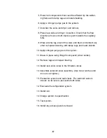
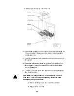
9. Lift the TCA straight up out of the unit.

10. Inspect the insulation on the inside of the case walls while the

TCA is removed. Replace any that is wet.  Install insulation
on the new TCA.

11. Transfer the strainer from inside the old TCA to the new TCA,

if required.

12. Clean the refrigeration stubs on the new TCA carefully prior

to installation. Clean the inside of the mating copper lines
prior to installation.

13. Lower the TCA into place and secure the mounting flange to

the mounting rails.

CAUTION: The refrigerant inlet and outlet lines are stain-
less steel. They are easily damaged by excessive heat.
Solder the fittings as follows:

A. Ensure all fittings have been carefully cleaned.

B. Apply a paste-type flux.

Содержание NESLAB HX 150

Страница 1: ...n Service Thermo Manual P N U00058 Rev 09 09 97 NESLAB HX 150 Recirculating Chiller No part of this publication may be reproduced or reprinted except for personal use without the prior permission of Thermo Electron ...

Страница 2: ...oid valve 15 Tank coil assembly TCA 17 Water regulating valve 21 Capillary tube 23 Refrigeration components general 25 Procedures Speed check 27 Suction Discharge pressure and speed check 28 Condenser maintenance air cooled water cooled 29 Flushing closed facility system 29 Flushing tap water system 30 Flushing unit off 31 Commercial flushing chemicals 32 Hot gas valve Automatic Discharge Relief A...

Страница 3: ...e Refrigeration Specifications 44 R22 pressure temperature chart 45 Heat load calculation 46 Condenser requirements Air cooled units 47 Condenser requirements Water cooled units 48 15 pin accessory connector optional pinout 49 Part numbers 50 3 ...

Страница 4: ... unprotected flesh 3 Refrigerant gases are not flammable and are chemically inert However they are heavier than air and will displace oxygen They can cause suffocation if released in a confined area 4 Refrigerant gases used in this product are classified as Ozone Depleting Chemicals by the US Environmental Protec tion Agency While they pose no hazard sealed inside the refrigeration system intentio...

Страница 5: ...r no load This duty cycle will reverse as increasing load is applied reaching 100 COOL 0 HEAT IDLE at full load This system results in tighter temperature control than continu ally cycling the compressor on and off as is typical in a house hold refrigerator The default mode is HEAT IDLE A failure of the temperature sensor or controller will generally result in the HEAT IDLE mode This prevents a po...

Страница 6: ...ressed HEAT IDLE MODE If the setpoint is above the actual temperature the controller is in HEAT IDLE mode The triac output opens turning the solenoid coil off The solenoid valve then drops closed This closed valve stops the flow of refrigerant During the heat idle mode when the liquid line solenoid valve is closed the pressure drops in the suction line back to the compressor When the pressure drop...

Страница 7: ... coil from valve Drawing 67 cfl Rick Mills 13 March 1995 YES YES NO Valve is stuck open Not a Refrigeration Problem Problem is in Controller or sensor See VALVE REPLACEMENT Does unit warm up YES NO UNSURE YES NO NO Can you get cool lamp off Is coo l lamp on by manipulating setpoint Is coil on No rmal Response Troubleshooting Chart Runaway cold ...

Страница 8: ...995 YES NO Valve is stuck closed Not a refrigeration problem See VALVE REPLACEMENT UNSURE Can you get cool lamp on Is cool lamp on YES NO NO YES NO YES NO YES NO YES by manipulating setpoint See TROUBLESHOOTING WEAK COOLING Any DC volts on coil Any AC volts on coil Is coil on Problem is in Controller or Sensor Is it cooling at all Troubleshooting Chart Runaway hot ...

Страница 9: ...9 Troubleshooting Chart Weak cooling ...

Страница 10: ...10 Troubleshooting Chart Weak cooling continued ...

Страница 11: ...11 Troubleshooting Chart Refrigeration pressures ...

Страница 12: ... may be compared to the replacement compressor 3 Recover the system refrigerant 4 Disconnect wires starting devices etc from compressor 5 Remove valve cores from both Shrader valves 6 Remove the coil from the solenoid valve and move it out of the torch area Wrap a damp rag around the solenoid valve body 7 Unsolder and remove compressor and dryer NOTE If a compressor burnout is suspected invert old...

Страница 13: ...m the old com pressor and insert it into the new compressor 10 Apply nitrogen purge gas to the stem 11 Braze in place using BAg 28 silver solder compound 12 Position the new compressor in place 13 Position the new dryer in place Ensure the flow direction arrow points toward the solenoid valve 14 Wrap a damp rag around the dryer 15 Apply nitrogen purge gas to the suction service port 16 Braze the s...

Страница 14: ...d orientation of the electrical wiring for installation 3 Disconnect the electrical wiring 4 Unbolt the fan from the base of the condensing unit 5 Pull the fan assembly motor blade and bracket out of the unit 6 Transfer the blade conduit and or bracket to the new motor 7 Reassemble in reverse order ...

Страница 15: ...round the solenoid valve body 4 Apply purge gas to the system 5 Desolder and remove old filter dryer 6 Place new filter dryer in position with direction of flow arrow pointing towards the liquid line solenoid valve 7 Wrap the filter dryer body in a damp rag 8 Introduce nitrogen purge gas into the discharge service port 9 Braze connections using BAg 28 Orient torch flame away from the filter dryer ...

Страница 16: ... voltage 1 Recover refrigerant 2 Remove coil 3 Remove all valve cores from the Shrader valves 4 Note the direction of flow so that the new valve can be prop erly positioned during assembly Disassemble solenoid valve and remove internal components as shown below ...

Страница 17: ...nd protect any other components wiring with damp rags and metal shields 10 Apply nitrogen purge gas to the system 11 Braze in place using BAg 28 compound silver solder 12 Remove rags and inspect brazing 13 Install new valve cores in the Shrader valves 14 Assemble solenoid valve assembly Use two wrenches and do not over tighten 15 Pressurize system and leak check The solenoid valve is closed so be ...

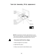
Страница 18: ... separated The following procedure assumes that the pump along with its plumbing has been removed Disconnect unit from line voltage 1 Recover refrigerant if any remains 2 Drain fluid from system 3 Remove valve cores from both Shrader valves Tank Coil Assembly TCA replacement ...

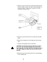
Страница 19: ...nlet and outlet stubs 6 Remove the insulation from the refrigerant inlet and outlet lines 7 Unsolder the refrigerant inlet and outlet lines CAUTION The refrigerant inlet and outlet lines are stain less steel They are easily damaged by excessive heat Never apply the torch flame directly to the stainless Warm the copper fittings up slowly and evenly until the solder liquefies 8 Remove the four screw...

Страница 20: ...f required 12 Clean the refrigeration stubs on the new TCA carefully prior to installation Clean the inside of the mating copper lines prior to installation 13 Lower the TCA into place and secure the mounting flange to the mounting rails CAUTION The refrigerant inlet and outlet lines are stain less steel They are easily damaged by excessive heat Solder the fittings as follows A Ensure all fittings...

Страница 21: ...solder CAUTION The stainless must never be hot enough to turn cherry red This will cause oxidation and the solder will not wet the oxidized material If this oc curs stop immediately Allow fittings to cool Polish the stainless fittings with emery cloth until all traces of dark oxidation are removed 14 Disconnect nitrogen purge gas 15 Install new valve cores in the Shrader valves 16 Pressurize syste...

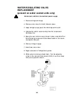
Страница 22: ...port 4 Unbraze the valve s sensor pickup from the compressor discharge line 5 Braze the new valve s sensor pickup in place using BCuP3 or BCuP5 brazing compound Silver based solder is not recom mended for this joint 6 Remove nitrogen supply 7 Install new valve cores 8 Begin evacuation of refrigeration system 9 While system is being pumped down Turn the adjusting screw on the old valve fully closed...

Страница 23: ...to new valve 13 Mount new valve using the two unions 14 Turn the adjusting screw on the new valve fully closed 15 Now back it out the number of turns observed in the previous step This will approximate the correct setting 16 Pressurize system and leak check 17 Evacuate system 18 Recharge refrigeration system 19 Test ...

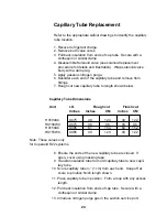
Страница 24: ...h shown below Capillary Tube Dimensions Unit I D Rough cut Finish cut Inches Inches CM Inches CM HX100AC 0 075 49 124 48 122 HX100WC 0 075 39 98 38 96 HX150AC 0 085 61 154 60 152 HX150WC 0 085 49 124 48 122 Note These values only for Copeland R22 systems 8 Ensure the ends of the new capillary tube are closed If open cover using masking tape 9 Transfer insulation tube from old capillary tube to new...

Страница 25: ...g the end of the capillary tube Silver type solder BAg28 is not recom mended for capillary tube connections 15 Braze the lower end to the capillary tube to the solenoid valve in a similar manner 16 Remove the damp rag nitrogen purge and the clips holding the insulation back 17 Reassemble solenoid valve 18 Insert new valve cores 19 Pressurize and leak check 20 Evacuate system 21 Charge system Capil...

Страница 26: ... is shown in the Solenoid valve replacement procedure and remove the internal components for purging Place the nut and stem back on the valve and secure snugly 7 Protect all components that could be damaged during braz ing with damp rags and or metal shielding 8 Apply a slow nitrogen gas purge 9 Unsolder all components being changed and remove 10 Remove nitrogen purge NOTE All components should be...

Страница 27: ...razing joints 17 Assemble solenoid valve s internal parts this procedure is shown in the Solenoid valve replacement procedure 18 Install new valve cores 19 Pressurize the system and check for leaks Be sure to pres surize both sides of any solenoid valve and the high and low side of the system 20 Evacuate the refrigeration system 21 Charge the refrigeration system to specifications 22 Test the unit...

Страница 28: ... the DROP figure from the table For example the HX100 with a PD 1 pump has a drop of 1 4 C 2 Divide the drop in half Example 0 7 C 3 Add this half to 20 C to find the START point Example 20 7 C 4 Subtract this half from 20 C to find the STOP point Ex ample 19 3 C Now the entire drop is centered about 20 C 5 Connect the unit s inlet and outlet with as short a loop of hose as practical Insert a ther...

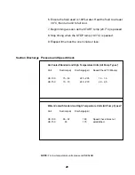
Страница 29: ...ute or less Suction Discharge Pressure and Speed Check Air Cooled Standard and High Temperature Units All Pump Types 1 Unit Suction psi Discharge psi Speed Check C Minute HX 100 75 83 245 265 1 3 1 6 HX 150 70 73 240 270 2 0 2 5 Water Cooled Standard and High Temperature Units All Pump Types 2 Unit Suction psi Discharge psi HX 100 86 92 180 Speed check times not HX 150 65 175 established NOTE For ...

Страница 30: ... any bent fins using a fin comb Condenser Water cooled The water cooled condenser generally needs no maintenance If the cooling water is particularly dirty deposits may occur and cause flow restrictions In this event flushing may be required The procedure used depends on whether a closed facility water cooling system or a tap water system is used The procedures are described on the following pages...

Страница 31: ...nd to loosen any deposits Cooling performance may be less and the water regulating valve may make some vibration noise 6 Turn HX off 7 Close valves on cooling water supply and return lines 8 Restore hoses to original configuration 9 Open valves on cooling water supply and return lines Flushing using a tap water system 1 Turn HX off 2 Close valve on cooling water supply line 3 Disconnect hoses from...

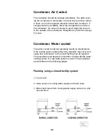
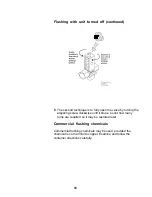
Страница 32: ...ither the closed facility or tap water system it is possible to flush the condenser even if it not possible or convenient to turn the HX on This method may be used for example if the HX is having other service or maintenance performed at the same time or if electricity is not available It is necessary to manually open the regulating valve to allow flow through the condenser There are two technique...

Страница 33: ...e by turning the adjusting screw clockwise until it stops Count how many turns are required so it may be restored later Commercial flushing chemicals Commercial flushing chemicals may be used provided the chemical is not harmful to copper Examine and follow the container directions carefully ...

Страница 34: ...enter of the base of the unit OPERATION This valve is closed during the cool cycle When the unit switches to heat cycle the solenoid valve in the liquid line closes and the resulting decrease in suction pressure opens the hot gas valve This provides a path for refrigerant gas to enter the evaporator directly without going through a liquid phase providing a heating effect HX150 BASE MOUNT TYPE HX10...

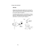
Страница 35: ...gas valve The valve is set correctly when the suction gauge indicates 25 PSIG for any system using R 22 refrigerant The setting is adjusted as shown in the illustrations Turning the adjustment clockwise will increase the pressure setting on either type valve Contact NESLAB Technical Service for setting specifications on systems using other refrigerants ...

Страница 36: ...whatever pressure is present in the refrigeration system The pressure across the diaphragm will equalize The diaphragm in the valve will cease to operate correctly as it expects to have ambient air pressure on one side Hot Gas Valve Leak Leak in Vertical Type If a leak is suspected check for leaks carefully where the ad justing screw enters the valve body If an internal leak occurs the refrigerant...

Страница 37: ... unit can now be operated temporarily with the dust cover removed but the leak still exists and needs repair Any further leak detection inside the adjustment chamber should only be done with an electronic sniffer type detector Do not use liquid detection fluid RESONATION It has been observed that certain base mounted hot gas valves have a mechanical resonance point If the valve is adjusted to that...

Страница 38: ...ptied of refrigerant NESLAB recommends replacing the valve cores with new ones as a preventive mea sure If a leak is suspected but cannot be confirmed with an elec tronic leak detector NESLAB recommends using a party bal loon to trap any escaping refrigerant This will provide a visual confirmation of a leak BALLOON TEST 1 Remove valve cover if installed 2 Stretch a balloon over the Schrader valve ...

Страница 39: ... C Apply one drop of the appropriate refrigeration oil to the flared surface of the cap to prevent galling Do Not Over Oil it will displace the sealant D Apply only one drop of sealant Perma Lok LM012 recommended NESLAB partnumber 013002 to the first thread of the valve and work it around at least half way but no more than one complete turn E Hand tighten cap until is seats Apply two wrenches one ...

Страница 40: ...ycle and release in the heat cycle If the coil never turns on either the coil is open or the control voltage is missing The coil can be tested for continuity using an Ohmmeter Turn the unit off Unplug the coil from the wiring harness and measure the coil resistance It should be 750 850 Ohms Replacements are available as a coil only or a coil assembly The assembly includes the electrical connector ...

Страница 41: ...large nut from valve body 4 Remove internal valve components 5 Inspect interior of valve body for cleanliness and lack of burrs or wear 6 Disassemble new valve and transfer components to the existing valve body 7 Install large nut onto valve body 8 Pressurize system and leak check As the valve is normally closed be sure that both sides of the valve are pressurized 9 Begin evacuation of system 10 I...

Страница 42: ...42 ...

Страница 43: ...e TCA should be replaced Tank coil assembly failure A hole developing in the evaporator of the Tank Coil Assembly can cause serious problems if not detected quickly Once a hole occurs refrigerant will escape into the circulating fluid Once the refrigerant is exhausted circulating fluid will be drawn in and contaminate the refrigeration system A hole in the evaporator may be recognized by a stream ...

Страница 44: ...utlet hose Allow it to run until all air is displaced 5 Turn setpoint to maximum The HX should enter the heat cycle 6 Adjust the valve stem closed CCW until the flow stops 7 Slowly open the valve stem CW until a small but constant trickle is exiting the outlet hose This is the point where the valve is just beginning to crack open This is the correct setting 8 Turn setpoint to minimum The HX should...

Страница 45: ...6 24 4 74 87 250 280 2 0 2 5 78 25 5 76 89 255 285 1 9 2 4 80 26 6 78 90 260 290 1 9 2 4 82 27 7 80 91 265 295 1 8 2 3 84 28 8 82 92 270 300 1 8 2 3 Conditions 1 Access panels removed 2 Water in reservoir 3 Circulating temp 27 C 81 F 4 Ambient measured at condenser intake Refrigerant specifications HX100AC HX100WC HX150AC HX150WC Refrigerant R22 Amount 22oz 20 oz 28 oz 24 oz Amount metric 624 g 56...

Страница 46: ...0 78 7 26 40 17 145 81 8 24 42 19 150 83 9 22 44 21 155 85 10 20 46 23 160 87 11 19 48 24 165 89 12 17 50 26 170 91 13 15 52 28 175 92 14 14 54 29 180 94 15 12 56 31 185 96 16 11 58 32 190 98 17 9 60 34 195 100 18 8 62 35 200 101 19 7 64 37 205 103 20 5 66 38 210 105 21 4 68 40 220 108 22 3 70 41 230 111 23 1 72 42 240 114 24 0 74 44 250 117 25 1 76 45 260 120 26 2 78 46 275 124 27 4 80 48 290 128...

Страница 47: ...47 ...

Страница 48: ...nt temperature of 35 C The unit must be positioned so the air intake and discharge are not impeded Air is drawn in through the left side of the unit and discharged through the right and rear A minimum clearance of 2 feet 0 6 meter on these three sides is necessary for ad equate ventilation Inadequate ventilation will cause a reduction in cooling capacity and in extreme cases compressor failure Exc...

Страница 49: ...t 4 0 gpm 15 lpm with a pressure differential of at least 10 psi 69 kPa A water regulating valve located in TAP WATER line regulates the flow rate of the cooling water supply as it enters the unit The valve regulates the flow rate based on the heat load Flow through the unit stops automatically when the unit is shut off HX100 Required flow gpm Required flow lpm Required pressure drop PSI Required ...

Страница 50: ...ound should only be used as a reference pin 7 Sensor temperature current limited through 2 7K OHM resistor The fluid temperature as measured by the controller s sensor located in the reservoir can be read at this pin The temperature scale is 10mV C referenced to analog ground pin 6 example 150mV 15 0 C 8 Setpoint out The present temperature setpoint can be read at this pin The temperature scale is...

Страница 51: ...51 ...
Отзывы: