Doc. 065214-02 1/12
3
Connect a Thermo Scientific
Dionex AS40 Automated
Sampler (Optional)
1. Place the AS40 to the left of the Dionex
ICS-900 on the workbench.
2. Route the outlet line from the AS40 through
the Dionex ICS-900 left side slot to the
injection valve.
3. Connect the outlet line from the AS40 to
port
S
on the injection valve (see
4. Locate the relay control cable (P/N 047946)
supplied with the AS40.
5. Remove the 2-position connector plug from
the pair of wires labeled
LOAD
on the relay
control cable.
6. Locate the 12-position connector plug
(P/N 923686) in the Dionex ICS-900 Ship Kit
(see
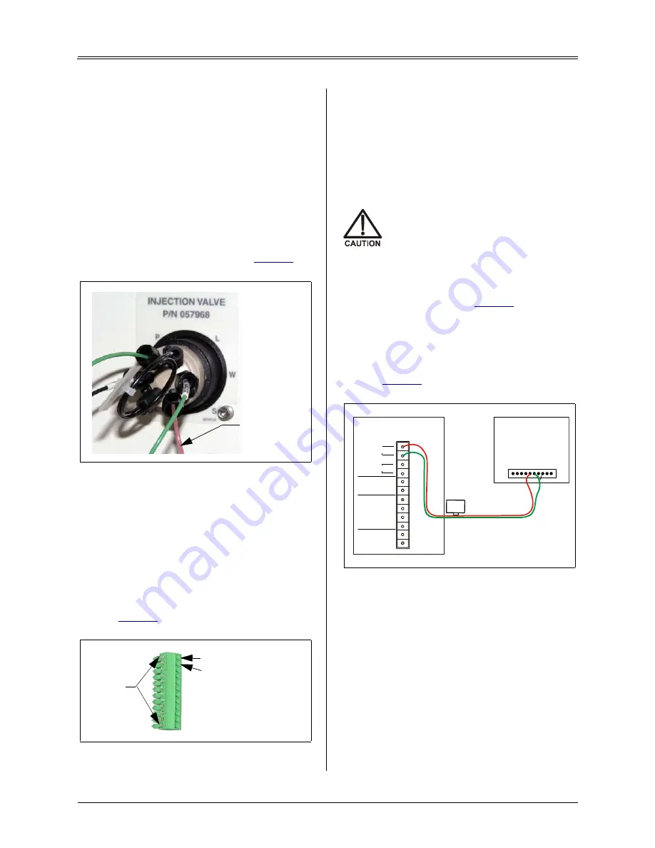
7. Attach the red wire from the relay control
cable to the first position on the plug, and
attach the green wire to the second position.
To attach a wire to the plug, strip the end of
the wire (if necessary), insert it into the plug,
and use a screwdriver to tighten the locking
screw.
When attaching wires to the connector
plug, be careful not to allow stray
strands of wire to short to the adjoining
position on the connector.
8. Plug the 12-position connector plug into the
TTL and relay connector on the Dionex
ICS-900 rear panel (see
). Make sure
the wires connect to the
RELAY OUT 1
pins.
9. Plug the AS40 relay control cable's 10-
position connector plug into the
RELAY
CONTROL
connector on the AS40 rear panel
Unpack the PC
(If supplied by Thermo Fisher
Scientific)
1. Remove the PC and all documentation from
the PC box and place them on a workbench.
2. Follow the instructions in the PC installation
guide to connect the PC components.
Figure 5. Dionex ICS-900 injection valve
Figure 6. 12-position connector plug
AS40
Sample
Outlet Line
Locking
Screws
Connect green wire here
Connect red wire here
Figure 7. Example AS40 Automated Sampler
connection
Relay Control Cable
RELAY CONTROL
R
EAD
Y
O
U
T
GN
D
F2
LO
A
D
GN
D
GN
D
CB
L
P
R
E
S
E
NT
GN
D
+
5
V
DC<
5
0
M
a
GN
D
AS40 Rear Panel
ICS-900 Rear Panel
TTL/Relay Connector
red
green
1
2
(+)
TTL OUT
1
2
TTL GND
(-)
1
2
3
4
TTL IN
(+)
1
2
RELAY
OUT
red green
Load


