background image

ECO

DESCRIPTION

REV

authorized by Thermo.

TOLERANCE UNLESS SPECIFIED:

ALL DIMENSIONS ARE IN MILLIMETERS AND [INCHES]

CHECKED BY:

DATE:

3

3

B

A

BY

C

D

4

B

PROJECTION

2

REMOVE ALL BURRS & UNNECESSARY

SHARP EDGES

PART NUMBER:

ENGINEER:

1

DRAWING NUMBER

SIZE

SCALE

DATE:

SHEET

REV

A

C

1

2

4

APP

DATE

D

This document is confidential and is the property of Thermo Fisher 

Scientific ("Thermo"). It may not be copied or reproduced in any 

manner without the expressed written consent of Thermo. This 

document also is an unpublished work of Thermo. Thermo intends to 

and is maintaining the work as confidential information. Thermo also 

may seek to protect this work as an unpublished copyright. In the 

event of either inadvertent or deliberate publication, Thermo 

intends to enforce it's rights to this work under the copyright laws as 

a published work. Those having access to this work may not copy, 

use or disclose the information in this work unless expressly 

DATE:

DMG

DMG

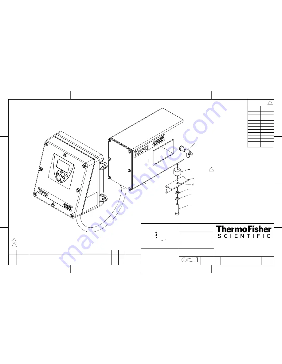
APEX 300 OUTLINE AND MOUNTING

5/31/07

5/31/07

810108

© 2007, by Thermo Fisher Scientific

Derived From:  

07387M-B300


B

1 of 5

1:3

DMG

5/31/07

B

1423

RLK

12/21/07

DG

RELEASED

A

X         

X.X      

X.XX    

ANGLES    

DRAWN BY:

M10 WASHER

ISOLATOR FOOT    2

INSULATING BUSHING

M10 SCREW

SHEET 2)

DIMENSIONS

AUDIT CHECK

(OPTIONAL,


SUPPORT FRAME, TYPICAL

12.7[.50] THRU

1


NOTES:

STANDARD ISOLATOR FOOT LENGTH IS 25.4[1.00].

1.

CABLES LONGER THAN 30M [98.4 FT] AVAILABLE AS A SPECIAL ORDER (UP TO 90M [295 FT]).

2.


AVAILABLE         

CABLE LENGTHS         

METERS

FEET

.5

1.6

2

6.6

3

9.8

4

13.1

5

16.4

6

19.7

8

26.2

10

32.8

12

39.4

15

49.2

20

65.6

25

82.0

30

98.4

B

2739

ADDED APERTURES SIZES 275,300,325,350

RLK

RLK

10-14-10

Содержание APEX 100

Страница 1: ...Thermo Scientific APEX Metal Detector User s Guide REC 4248 Rev K Part number 085381 English ...

Страница 2: ...Page 2 Thermo Scientific APEX User s Guide 2009 Thermo Fisher Scientific Inc All rights reserved For future reference write your APEX serial number below APEX serial __________________________________ ...

Страница 3: ...cts 32 Setting Product Parameters 35 Keying In the Pack Length 35 Keying In the No Pack Distance 37 Disabling the Detection No Pack Function 38 Keying In the Pack Gap 40 Setting Reject Parameters 43 Keying In the Distance to the Reject Device 44 Keying In the Signal Duration for the Reject Device 46 Setting Contaminant Detection Parameters 47 Establishing Noise Thresholds with No Product Present 4...

Страница 4: ...ration Timing 97 Setting the Reject Delay Time 98 Setting the Reject Duration Time 99 Setting Contaminant Detection Parameters 101 Establishing a Baseline with No Product Present 101 Choosing the Correct Speed Filter Settings for the Rx 104 Establishing Basic Product Parameters 105 Set Up Check List for Pharmaceutical Applications 108 Parameters You Have Already Set Up 108 Additional Parameters Yo...

Страница 5: ...the Reject 2 Device 142 Keying In the Signal Duration for the Reject 2 Device 142 Assigning Tasks to the Reject 2 Device 143 Setting the Latching Reject Function for Reject 2 144 Inverting the Reject Function for Reject 2 144 Rejects Menu Page 6 145 Entering a Reject Confirm Time for the Reject 2 Device 145 Calibrating the Reject 2 Confirm Time 147 Phase Angle Page 1 150 Calibrating the Phase Angl...

Страница 6: ...Tools Page 5 193 Displaying Your Software Version 193 Displaying Your APEX Model Type 194 Displaying Your System Set Up Code 194 Displaying Your Product Set Up Code 195 Quality Test 196 Overview of How the Quality Test Function Works 197 Testing the Detector Using QA Test Samples 198 Setting the Time Interval Between QA Tests 200 Setting the Time Window for Doing a QA Test 201 Setting the Reject D...

Страница 7: ...of an Output Device 236 Printer Set Up Page 1 238 Attaching a Printer to the Detector 238 Navigating to the Printer Set Up Menu 239 Activating the Printer 241 Manual Printing 242 Naming Your Detector 243 Naming Your Product Batches 244 Printer Set Up Page 2 245 Activating an End of Day Print Out 245 Activating a Reject Print Out 246 Activating a Print Out on Power Up 247 Security Level 249 Enterin...

Страница 8: ... Software 325 Configuring a TCP IP Network 325 Accessing the TCP IP Communications Menu 326 Changing the DHCP Default Setting During Installation 329 Changing DHCP to Off 329 Manually Changing Communication Parameters 330 Changing the IP Address 330 Changing the Subnet Mask Address 331 Changing the Gateway Address 332 MAC Addresses 332 Saving Your TCP IP Settings 333 Changing DHCP to On 334 Config...

Страница 9: ...itical APEX Settings 355 Detailed List of Modbus Registers 357 Appendix B IntelliTrack XR 367 Overview 369 System Requirements 369 Product Requirements 369 Discussion of Product Requirements 370 Setting Up Related Functions 371 Keying In the Pack Length 371 Keying In the Detection No Pack Distance 372 Keying In the In Feed Photo Eye Distance 374 Enabling Photo Eye Registration 376 Enabling the IXR...

Страница 10: ...Page 10 Thermo Scientific APEX User s Guide ...

Страница 11: ...s global parameters are ones that you will not change very often In contrast application specific parameters are ones you use to get your particular type of application conveyor gravity feed pipeline or pharmaceutical set up and running properly Application specific parameters sometimes need to be fine tuned to optimize the detector s performance for your particular operating environment Setting P...

Страница 12: ...ch head is installed around the outside of the duct Pipeline Applications The detector s search head is installed surrounding a pipe where product is flowing under pressure Pharmaceutical Applications The search head surrounds a chute where the product drops through the chute under the influence of gravity The detector s search head is installed around the outside of the chute Choosing Your Applic...

Страница 13: ...t Parameters In this section you will learn how to Key in pack length Key in no pack distance Key in pack gap Setting Product Reject Parameters In this section you will learn how to Key in the distance to the product reject device Key in the signal duration for the product reject device Calibrating Your Detector In this section you will learn how to Establish a noise threshold with no product pres...

Страница 14: ...bal set it and forget it parameters language help text and units of measure Understanding the Detector s Control Panel The main components of the detector s control panel are as follows The display panel The three red green and yellow indicator lights The green Go button The red Back button The four blue triangular shaped navigation buttons The detector s control panel looks like this ...

Страница 15: ... numbers and select characters and settings in various menus and input screens The Go Button Press the Go button to select or start one of the detector s functions The Back Button Press the Back button to stop one of the detector s functions or to return to the previous menu screen Pressing the Back button repeatedly will always take you back to the detector s Main Menu Using the Detector s Button...

Страница 16: ...s on Using the Detector s Sub Menus Here are some tips to help you navigate the detector s menus and access all of its functions Use the navigation buttons on the control panel to navigate to and highlight the function you want to use Press the Go button to access the function If pressing the Go button does not work try the down navigation key because some functions menus and options are accessed ...

Страница 17: ...n you are going to learn to navigate around some of the detector s menus and input screens More specifically you are going to set up a number of global parameters for the detector Global parameters are ones you set at the start of a project because this type of parameter once set does not often need to be changed You are going to do the following Choose the language shown in the display panel Remo...

Страница 18: ...s 2 Press the navigation buttons to select the system and tools menu as shown below 3 Press the Go button and page 1 of the system and tools menu appears Notice the notation 1 5 in the screen above This tells you that you are currently on page 1 in the system and tools menu which is five pages long ...

Страница 19: ...at they look like Select page 4 which is shown below 5 Press the right navigation button to select English 6 Press the Go button repeatedly to scroll through the available languages and select the language you want displayed 7 To exit and have the detector use the language you chose in Step 6 press the Back button repeatedly until you return to the Main Menu ...

Страница 20: ...ning screen appears just press the Back or Go buttons to clear it Displaying Help Text In the Main Menu the default setting is to display a bar graph at the top of the screen You are now going to change this setting so that Help Text is displayed The Help Text provides a brief description of the screen you are looking at which makes navigating and using the detector s functions much easier 1 Make ...

Страница 21: ...lowing screen appears 6 Press the Go button once to toggle the screen from the bar graph setting to the Help Text setting Notice that descriptive Help Text is now displayed at the top of the screen and will continue to be displayed until you change this setting Bargraph and Help Setup 7 Press the Back button repeatedly to return to the Main Menu ...

Страница 22: ...uctions to the set units you prefer to use and have the detector display 1 Make sure the detector s Main Menu is displayed Product Name 2 Use the navigation buttons to select the system and tools menu System and Tools 3 Press the Go button and page 1 of the system and tools menu appears System and Tools Page 1 4 Press the down navigation key and page 2 of the system and tools menu appears System a...

Страница 23: ...perial function Metric Imperial Units 6 Press the Go button to toggle between imperial and metric units Highlight the units of measure meters or feet and inches you prefer to use 7 To exit and select the units you chose in Step 6 press the Back button repeatedly until you get back to the Main Menu ...

Страница 24: ...or analysis On the other side of the detector contaminated packets are pushed off the conveyor into a rejects bin by a mechanical arm your reject device A photo electric cell photo eye attached to the detector monitor the flow of packets on the conveyor This is photo eye number 1 which monitors the packets just before they enter the detector s search head This is a fairly typical set up for a conv...

Страница 25: ... control key The delete key The exit and save key All other keys are simple character entry keys and function exactly as they do on a computer keyboard The keyboard screen above shows the heading Exit Save because this is the key that is currently active in the screen as shown by its black highlight If you change the active key by using the navigation buttons in the detector s control panel the he...

Страница 26: ...l to select the appropriate letters and type in the heading SALTED BUTTER by navigating to the appropriate letter in the keyboard and pressing the Go button on the detector s control panel Use the keyboard s Space key to create the gap between the two words When finished your keyboard screen should look like this 7 Highlight the exit and save key using the navigation buttons on the detector s cont...

Страница 27: ...ing the Product section Keying In the Product Speed This section assumes the conveyor belt is running and that you have already calculated its speed in either feet per minute or meters per minute using a mechanical tachometer Before proceeding make sure you have already set your preferred units of measure metric or imperial and that these are currently being displayed in the detector s display pan...

Страница 28: ...d and exit the input screen 5 Note that the speed of the conveyor is now displayed in the product speed section of the Main Menu Keying In the Photo Eye to Detector Distance The photo eye to detector distance is a critical parameter that must be entered to ensure your conveyor application works correctly 1 Take a tape measure and note the distance from the photo eye on the upstream or in feed side...

Страница 29: ...enu System and Tools Page 3 5 Navigate to the photo eye set up menu PE distance and head width 6 Press the Go button and page 1 of the Photo Eye Distance and Head Width menu appears PE distance and head width 7 Press the right navigation button to select the In Feed Photo Eye Distance menu Infeed Photo Eye Distance ...

Страница 30: ...cells can send a signal to the detector either when it detects light or when it detects dark A light activated photo cell sends a signal when light is detected and a dark activated photo cell sends a signal when dark is detected You need to tell the detector which type of photo cell you are using If you do not know for sure key in a positive polarity in the input menu screen step 7 below and if th...

Страница 31: ...the inputs menu Inputs 5 Press the Go button and page 1 of the input set up menu appears Input Setup 6 Navigate to the Infeed Photo Eye Input menu shown below Infeed Photo Eye Input Look carefully at the 2 notation in this menu which tells you two things The in feed photo eye is connected to Input 2 on the detector s wiring board The input voltage has a positive polarity ...

Страница 32: ...e input screen Selecting the Correct Photo Registration for Rejects If you are using a photo eye to control your reject device this function allows you to do the following Make accurate and consistent rejects using a variety of reject devices such as drop nose retracting belt air pusher and air reject systems Make accurate and consistent rejects even when the gaps between your individual units of ...

Страница 33: ...best photo registration setting for your particular application Leading Edge Rejects This setting is recommended for drop nose and retracting belt reject devices Middle of the Product Rejects This setting is recommended for air pusher and air jet reject devices Entire Length Rejects This setting is recommended for applications where the gaps between the units of product are variable When gaps vary...

Страница 34: ... saves your previous setting Leading Photo Registration 5 Press the Go button repeatedly until a check mark appears beside the type of photo registration you want to use These options are mutually exclusive Press the Back button to save your setting and exit the menu Reject is triggered by the product s leading edge Reject is triggered by the center of the product This is the recommended setting f...

Страница 35: ...rameters for your conveyor application Keying In the Pack Length The length of the individual units of product moving along the conveyor for example packets of salted butter is referred to as the pack length of the product 1 Make sure the Main Menu is displayed Product Name 2 Press the Go button and page 1 of the product menu appears Product Calibrate and Name 3 Press the down navigation button to...

Страница 36: ... you would now measure the length of the product you are testing and key this value into the pack length input screen using the navigation buttons In our example we measured the length of our packets of salted butter noted that they are 12 4 centimeters in length and have keyed in this number into the input screen as shown below Pack Length 7 Press the Go button to save your pack length setting an...

Страница 37: ...the packs is contaminated In most conveyor applications it is best to enter identical values for the pack length and the no pack distance functions 1 Make sure the no pack distance function is highlighted Detection no Pack distance 2 Press the Go button and an input screen appears Detection no Pack distance 3 Key in the same value you entered for the pack length parameter In our example where we a...

Страница 38: ... a contaminant is detected that is not associated with a package Detection no Pack To disable the detection no pack function do the following 1 Make sure the Main Menu is displayed Product Name 2 Navigate to the systems and tools menu and make sure it is highlighted System and Tools 3 Press the Go button and page 1 of the system and tools menu appears System and Tools Page 1 continued ...

Страница 39: ...ars Warnings Alarms Faults 6 Press the down navigation button and page 2 of the menu appears Warnings Alarms Faults 7 Navigate to the detection no pack function and make sure it is highlighted Detection no Pack Note that currently when the APEX detects a contaminant that is not associated with a package a fault results as shown by the presence of the fault symbol in the menu ...

Страница 40: ...her is contaminated Pack Gap Example Let us assume the following You are testing multiple units of product packs or packets in a conveyor application where the length of the gap between the packs is about the same as the pack length The pack gap function is currently set to the detector s default value of 100 In this type of conveyor application where you are testing multiple units of product such...

Страница 41: ... detector using input from the photo eye on the conveyor or they can be set by you the user as described above Thus by setting appropriate values for the pack gap function the detector will take one of the following actions Reject Pack 1 only Reject both packs Reject Pack 2 only The following table illustrates what action the APEX will take when a contaminant is detected in one of the positions A ...

Страница 42: ...menu follow steps 1 4 in the Keying In the Pack Length section above to reach this menu Product Shape and Flow 2 Use the navigation buttons to select the pack gap menu Pack Gap 3 Press the Go button and the pack gap input screen appears Pack Gap 4 Key in an appropriate value for pack gap In our example we have keyed in a value of 50 Pack Gap 5 Press the Go button to save your pack gap setting and ...

Страница 43: ...surements You Will Need Before Starting Imagine our packets of salted butter moving along the conveyor and the search head suddenly detects a packet containing a metallic contaminant For now the contaminated packet continues its journey out of the search head and along the conveyor Around one meter from the detector however the packet passes the main reject device and is suddenly ejected from the ...

Страница 44: ...1 Distance Delay function Reject 1 Distance Delay Stop and look very carefully at the highlighted number in the screen above and note that the current setting is 0 300 meters as shown by the m after the number In other words the reject distance is not expressed in seconds which for some applications would be a valid setting a If the number in the Reject 1 Distance Delay menu is shown as a time uni...

Страница 45: ...shown in step 3 is displayed the one where the reject distance is expressed in meters You are now ready to key in your reject distance in meters or feet and inches if these are your preferred units 4 Press the Go button and the reject distance input screen appears Use the navigation buttons to key in your reject distance In our salted butter example we have entered our reject distance of 1 17 mete...

Страница 46: ... to get there 2 Navigate to the reject device signal duration function Reject 1 Duration The screen above shows that currently the reject 1 device remains active for 1 50 seconds 3 Press the Go button and the signal duration input screen appears Use the navigation buttons to key in your signal duration in seconds and hundredths of a second In our salted butter example we have entered our signal du...

Страница 47: ...n you pass the 4 0 millimeter test stick use a smaller size Have the detector learn the appropriate detect level phase angle and peak signal settings by passing uncontaminated product through the search head Have the detector do a Quality Test learn if applicable Have the detector do an AuditCheck learn if applicable Once you have finished this section your detector will be set up and ready to go ...

Страница 48: ...d page 1 of the Frequency Gain Inhibit menu appears Frequency Gain Inhibit 4 Press the down navigation key to select page 2 of the frequency and gain menu Detection level and Noise 5 Navigate to the Calibrate Noise Thresholds menu Note The background of the calibrate function is now highlighted in black Calibrate Noise Thresholds ...

Страница 49: ...pplication As a general rule as the severity of the vibration increases the X threshold also increases Thus if higher conveyor speeds cause the X threshold to increase vibration is the likely cause Possible remedies include making sure the detector is completely isolated mechanically from your conveyor and or installing shock mounts for the detector Reducing High R Noise Thresholds An R threshold ...

Страница 50: ... 1 4 in the Choosing Your Preferred Units of Measure section on page 22 to get to the menu shown below page 2 of the system and tools menu System and Tools Page 2 2 Press the right navigation button to select the speed filter menu Speed Filter 3 Press the Go button and the calibrate filter menu appears Calibrate Speed Filter 4 Start up the conveyor and have the ferrous test stick ready If you are ...

Страница 51: ... the conveyor upstream of the detector so that the test stick passes through the center not the edge of the search head 7 When the calibration is complete the following screen appears showing the new setting for the speed filter The value shown in your screen will probably be different because the setting depends on belt speed and aperture size of the search head Speed Filter Setup ...

Страница 52: ...n function which sets the following basic parameters for your product Frequency and gain Phase angle setting Detect level AuditCheck parameters if applicable Setting Frequency and Gain to High Before doing a full product calibration it is best to set the detector s frequency and gain settings to high To do this follow the instructions below 1 Make sure the Main Menu is displayed Product Name Or li...

Страница 53: ...n menu and make sure it is highlighted Frequency and Gain Or like this when IXR is enabled Frequency and Gain 3 Press the Go button and page 1 of the frequency and gain menu appears Frequency Gain Inhibit 4 Press the right navigation button to highlight the gain menu Low High Gain ...

Страница 54: ...n to save your setting and return to page 1 of the frequency and gain menu Frequency Gain Inhibit 7 Navigate to the frequency menu Low High Frequency 8 Make sure a checkmark is showing next to the high frequency icon which looks like this High frequency icon Note If the checkmark is next to the low frequency icon press the Go button to select the high frequency setting 9 Press the Back button repe...

Страница 55: ...roduct calibration follow the instructions below 1 Make sure that the conveyor is turned on and uncontaminated product is passing through the search head In the example below we are monitoring jars of spaghetti sauce 2 Highlight your product name in the Main Menu Your screen will look different if IXR is enabled Product Name 3 Press the Go button and page 1 of the product menu appears Product Cali...

Страница 56: ...e detector s auto calibration function as shown by the icons and check marks in the screen above is now ready to do the following Learn the phase angle Learn the detect level Conduct an AuditCheck if this optional hardware is installed on your APEX 5 Press the Go button and the Performing Full Learn monitor screen appears Performing Full Learn continued ...

Страница 57: ...best option the high frequency low gain option a High Frequency Low Gain Option High Frequency Low Gain b Press the Go button to restart the full product calibration If this setting is too sensitive the following screen appears the low frequency high gain option c Low Frequency High Gain Option Low Frequency High Gain Please note that if the frequency is changed the APEX must relearn the X and R n...

Страница 58: ... note that this change in gain will result in the R and X noise thresholds being reduced by a factor of 4 f Press the Go button to restart the full product calibration If this setting is still too sensitive the following warning screen appears When this happens please contact Thermo Fisher Scientific as described in the Contacting Thermo Fisher Scientific section at the end of the manual Saturatio...

Страница 59: ...on has learned the following basic parameters for our uncontaminated product in our example jars of spaghetti sauce Detect level 53 Phase angle 2 24 What the Main Menu Screen Is Telling You The Main Menu screen is now telling you that once the detector is monitoring your product stream any unit of contaminated product that exceeds the detect level of 53 will be rejected And because the phase angle...

Страница 60: ...or press the left navigation button to change to a product with a lower product number Note that the product name bar will flash while you are choosing which product to change to and some of the relevant product settings will be displayed In the example below product 002 has been selected Product Name Confirm the Product Change Once you have selected the product you want to change to press the Go ...

Страница 61: ...isfaction Parameters You Have Already Set Up Listed below are the parameters you have already set up for a typical conveyor application Product Parameters Product name Pack length No pack distance Pack gap Conveyor and Photo Eye Parameters Conveyor belt speed Photo eye to detector distance Polarity of the photo eye input Photo registration for product rejects Reject Parameters Distance to the reje...

Страница 62: ... details see page 214 Quality Test A Quality Test allows you to verify that the detector is working properly especially when testing products over long periods of time The Quality Test is a manual not an automatic test For more details see page 196 AuditCheck If the optional AuditCheck equipment is installed on your search head the AuditCheck function allows you to verify that the detector is work...

Страница 63: ... how to Use the detector s display panel Navigate the detector s menus and sub menus Set up global parameters for the detector Key in a name for your product Setting Reject Parameters In this section you will learn how to Key in the reject delay time Key in the reject duration time Setting Contaminant Detection Parameters In this section you will learn how to Establish a noise threshold with no pr...

Страница 64: ...g Started section and read all the way through to the end of the Naming the Product section on page 26 When you have finished reading these sections you will know how to do the following Use the detector s display panel Navigate the detector s menus and sub menus Set up global parameters for the detector Key in a name for your product The Next Step Now that detour is over welcome back You are now ...

Страница 65: ...elay Time In most gravity feed applications where the gate is located close to the search head the reject delay time is usually set to 0 00 seconds Thus when the search head detects contaminants the gate closes immediately However in applications where the gate is located some way from the search head a time delay is needed because the product takes a finite time to move from the search head to th...

Страница 66: ...u appears Reject 1 Distance and Duration 3 Navigate to the reject 1 distance delay menu shown below Reject 1 Distance Delay 4 Press the Go button and the reject 1 distance delay input screen appears Key in an appropriate value for reject 1 distance delay For a typical gravity feed application key in a value of 0 00 seconds This allows the reject gate to close immediately when metallic contaminants...

Страница 67: ...to return to the Main Menu Setting the Reject Duration Time To set the reject duration time do the following 1 From the Main Menu navigate to the rejects menu Reject Totals 2 Press the Go button and page 1 of the rejects menu appears Reject 1 3 Navigate to the reject 1 duration menu shown below Reject 1 Duration continued ...

Страница 68: ...reject 1 duration input screen appears Reject 1 Duration 5 Key in a value for the reject 1 duration parameter For a typical gravity feed application key in a value of 1 00 6 Press the Go button to save your setting 7 Press the Back button repeatedly to return to the Main Menu ...

Страница 69: ...oduct is present in the duct Select the appropriate value for the speed filter Establish basic product parameters detect level and phase angle Once you have finished this section your detector will be set up and ready to go to work monitoring your product stream for the presence of metallic contaminants Establishing a Baseline with No Product Present Before you can establish a monitoring baseline ...

Страница 70: ...it menu appears Frequency Gain Inhibit 4 Press the down navigation key to select page 2 of the frequency and gain menu Detection level and Noise 5 Navigate to the Calibrate Noise Thresholds menu Note The background of the calibrate function is now highlighted in black Calibrate Noise Thresholds continued ...

Страница 71: ...there is a problem with excessive vibration in your application As a general rule as the severity of the vibration increases the X threshold also increases Possible remedies include making sure the detector is completely isolated mechanically from the surrounding duct and or installing shock mounts for the detector Reducing High R Noise Thresholds An R threshold in excess of 200 usually indicates ...

Страница 72: ...noise but still allows a maximum metal signal from the search head to be processed by the detector 1 Follow steps 1 4 in the Choosing Your Preferred Units of Measure section on page 22 to get to the menu shown below page 2 of the system and tools menu System and Tools Page 2 2 Press the right navigation button to select the speed filter menu Speed Filter 3 Press the Go button and the calibrate fil...

Страница 73: ...t the calibration process has set the speed filter to 25 00 Hz and the product speed to 234 meters per minute Calibrate Speed Filter Establishing Basic Product Parameters Before putting your detector into service you must have it learn how to identify your uncontaminated product This is done using the detector s full product calibration function which sets the following basic parameters for your p...

Страница 74: ...navigation button to highlight the Full Product Calibration menu Full Product Calibration The detector s auto calibration function as shown by the symbols and check marks in the screen above is now ready to do the following Learn the phase angle Learn the detect level Conduct an AuditCheck if this optional hardware is installed on your APEX continued ...

Страница 75: ...rent if IXR is enabled Product Name Notice that in our example the auto calibration function has learned the following basic parameters for our uncontaminated product Detect level 140 Phase angle 89 31 What the Main Menu Screen Is Telling You The Main Menu screen is now telling you that once the detector is monitoring your product stream any contaminated product that exceeds the detect limit of 14...

Страница 76: ...ts additional parameters you may want to set up to get your particular gravity feed application running to your satisfaction Parameters You Have Already Set Up Listed below are the parameters you have already set up for a typical gravity feed application Product Parameters Product name Reject Parameters Reject delay time Reject duration time Contaminant Detection Parameters Set by the Detector s C...

Страница 77: ...ure occurs the detector can stop the flow of product or notify you that a gate failure has occurred for example because the air supply to the gate has failed or product has built up on the gate or surrounding duct work For more details see page 137 Warnings Alarms and Faults WAFs Many of the detector s functions provide a warning alarm or fault when a condition needing your attention occurs This m...

Страница 78: ...Page 78 Thermo Scientific APEX User s Guide ...

Страница 79: ... to Use the detector s display panel Navigate the detector s menus and sub menus Set up global parameters for the detector Key in a name for your product Setting Reject Parameters In this section you will learn how to Key in the reject delay time Key in the reject duration time Setting Contaminant Detection Parameters In this section you will learn how to Establish a noise threshold with no produc...

Страница 80: ...ing Started section and read all the way through to the end of the Naming the Product section on page 26 When you have finished reading these sections you will know how to do the following Use the detector s display panel Navigate the detector s menus and sub menus Set up global parameters for the detector Key in a name for your product The Next Step Now that detour is over welcome back You are no...

Страница 81: ...close to the search head the reject delay time is usually set to 0 00 seconds Thus when the search head detects contaminants the valve closes immediately However in applications where the diverter valve is located some way from the search head a time delay is needed because the product takes a finite time to move from the search head to the diverter valve Clearly the reject delay time should be se...

Страница 82: ...enu appears Reject 1 Distance and Duration 3 Navigate to the reject 1 distance delay menu shown below Reject 1 Distance Delay 4 Press the Go button and the reject 1 distance delay input screen appears Key in an appropriate value for reject 1 distance delay For a typical pipeline application key in a value of 0 00 seconds This allows the reject gate to close immediately when metallic contaminants a...

Страница 83: ...to return to the Main Menu Setting the Reject Duration Time To set the reject duration time do the following 1 From the Main Menu navigate to the rejects menu Reject Totals 2 Press the Go button and page 1 of the rejects menu appears Reject 1 3 Navigate to the reject 1 duration menu shown below Reject 1 Duration continued ...

Страница 84: ...ject 1 duration input screen appears Reject 1 Duration 5 Key in a value for the reject 1 duration parameter For a typical pipeline application key in a value of 3 00 seconds 6 Press the Go button to save your setting 7 Press the Back button repeatedly to return to the Main Menu ...

Страница 85: ...uct is present in the pipe Select the appropriate value for the speed filter Establish basic product parameters detect level and phase angle Once you have finished this section your detector will be set up and ready to go to work monitoring your product stream for the presence of metallic contaminants Establishing a Baseline with No Product Present Before you can establish a monitoring baseline th...

Страница 86: ...it menu appears Frequency Gain Inhibit 4 Press the down navigation key to select page 2 of the frequency and gain menu Detection level and Noise 5 Navigate to the Calibrate Noise Thresholds menu Note The background of the calibrate function is now highlighted in black Calibrate Noise Thresholds continued ...

Страница 87: ...ere is a problem with excessive vibration in your application As a general rule as the severity of the vibration increases the X threshold also increases Possible remedies include making sure the detector is completely isolated mechanically from the surrounding pipe work and or installing shock mounts for the detector Reducing High R Noise Thresholds An R threshold in excess of 200 usually indicat...

Страница 88: ...gallons per minute R inside radius of the pipe Thus the flow rate in gallons per minute divided by the pipe s radius squared times 6 13 equals the product flow rate in feet per minute Fpm Please note however that in the examples given below product flow rates are expressed in meters per minute You can set the wide band filter to the following speeds This is the default setting and is used typicall...

Страница 89: ...ntific as described in the Contacting Thermo Fisher Scientific section at the end of the manual Setting Up the Speed Filter To set up the appropriate speed filter setting slow medium or fast do the following 1 Make sure the Main Menu is displayed Product Name 2 Navigate to the speed filter menu and make sure it is highlighted Slow Product Speed 3 Press the Go button repeatedly to scroll through th...

Страница 90: ...function which sets the following basic parameters for your product Phase angle setting Detect level Doing a Full Product Calibration To do a full product calibration follow the instructions below 1 Make sure product is flowing through the pipe 2 Highlight your product name in the Main Menu Your screen will look different if IXR is enabled Product Name 3 Press the Go button and page 1 of the produ...

Страница 91: ...e detector s auto calibration function as shown by the icons and check marks in the screen above is now ready to do the following Learn the phase angle Learn the detect level Conduct an AuditCheck if this optional hardware is installed on your APEX 5 Press the Go button and the Performing Full Learn monitor screen appears Performing Full Learn continued ...

Страница 92: ...in our example the auto calibration function has learned the following basic parameters for our uncontaminated product Detect level 202 Phase angle 1 46 What the Main Menu Screen Is Telling You The Main Menu screen is now telling you that once the detector is monitoring your product stream any contaminated product that exceeds the detect level of 202 will be rejected And because the phase angle is...

Страница 93: ...ts additional parameters you may want to set up to get your particular pipeline application running to your satisfaction Parameters You Have Already Set Up Listed below are the parameters you have already set up for a typical pipeline application Product Parameters Product name Reject Parameters Reject delay time Reject duration time Contaminant Detection Parameters Set by the Detector s Calibrate...

Страница 94: ...dition if the diverter valve fails the detector can stop the flow of product or notify you that a failure has occurred for example because the air supply to the valve has failed or miscellaneous residue has clogged the valve For more details see page 137 Warnings Alarms and Faults WAFs Many of the detector s functions provide a warning alarm or fault when a condition needing your attention occurs ...

Страница 95: ...arn how to Use the detector s display panel Navigate the detector s menus and sub menus Set up global parameters for the detector Key in a name for your product Setting Reject Parameters In this section you will learn how to Key in the reject delay time Key in the reject duration time Setting Contaminant Detection Parameters In this section you will learn how to Establish a noise threshold with no...

Страница 96: ... Started section and read all the way through to the end of the Naming the Product section on page 26 When you have finished reading these sections you will know how to do the following Use the detector s display panel Navigate the detector s menus and sub menus Set up global parameters for the detector Key in a name for your product The Next Step Now that detour is over welcome back You are now r...

Страница 97: ...t be set Reject Delay Time In most pharmaceutical applications where the gate is located close to the search head the reject delay time is usually set to 0 00 seconds Thus when the search head detects contaminants the gate closes immediately However in applications where the gate is located some way from the search head a time delay is needed because the product takes a finite time to move from th...

Страница 98: ... appears Reject 1 Distance and Duration 3 Navigate to the reject 1 distance delay menu shown below Reject 1 Distance Delay 4 Press the Go button and the reject 1 distance delay input screen appears Key in an appropriate value for reject 1 distance delay For a typical pharmaceutical application key in a value of 0 00 seconds This allows the reject gate to close immediately when metallic contaminant...

Страница 99: ...to return to the Main Menu Setting the Reject Duration Time To set the reject duration time do the following 1 From the Main Menu navigate to the rejects menu Reject Totals 2 Press the Go button and page 1 of the rejects menu appears Reject 1 3 Navigate to the reject 1 duration menu shown below Reject 1 Duration continued ...

Страница 100: ...eject 1 duration input screen appears Reject 1 Duration 5 Key in a value for the reject 1 duration parameter For a typical pharmaceutical application key in a value of 0 50 6 Press the Go button to save your setting 7 Press the Back button repeatedly to return to the Main Menu ...

Страница 101: ...roduct is present in the chute Select the appropriate value for the speed filter Establish basic product parameters detect level and phase angle Once you have finished this section your detector will be set up and ready to go to work monitoring your product stream for the presence of metallic contaminants Establishing a Baseline with No Product Present Before you can establish a monitoring baselin...

Страница 102: ...bit menu appears Frequency Gain Inhibit 4 Press the down navigation key to select page 2 of the frequency and gain menu Detection level and Noise 5 Navigate to the Calibrate Noise Thresholds menu Note The background of the calibrate function is now highlighted in black Calibrate Noise Thresholds continued ...

Страница 103: ...there is a problem with excessive vibration in your application As a general rule as the severity of the vibration increases the X threshold also increases Possible remedies include making sure the detector is completely isolated mechanically from the surrounding chute and or installing shock mounts for the detector Reducing High R Noise Thresholds An R threshold in excess of 200 usually indicates...

Страница 104: ...35 Speed filter 2 Medium the default Rx setting This is used typically for products flowing at a medium angle 35 Medium Product Speed However if you have products flowing at other standard angles 25 or 45 you should use a different speed filter as shown below Speed filter 1 Slow This is used typically for products flowing at a shallow angle 25 Slow Product Speed Speed filter 3 Fast This is used ty...

Страница 105: ...n at the end of the manual Establishing Basic Product Parameters Before putting your detector into service you must have it learn how to identify your uncontaminated product This is done using the detector s full product calibration function which sets the following basic parameters for your product Phase angle setting Detect level Doing a Full Product Calibration To do a full product calibration ...

Страница 106: ...e detector s auto calibration function as shown by the symbols and check marks in the screen above is now ready to do the following Learn the phase angle Learn the detect level Conduct an AuditCheck if this optional hardware is installed on your APEX 5 Press the Go button and the Performing Full Learn monitor screen appears Performing Full Learn continued ...

Страница 107: ...calibration function has learned the following basic parameters for our uncontaminated product Detect level 64 Phase angle 91 23 What the Main Menu Screen Is Telling You The Main Menu screen is now telling you that once the detector is monitoring your product stream any contaminated product that exceeds the detect level of 64 will be rejected And because the phase angle is 91 23 degrees the detect...

Страница 108: ...sts additional parameters you may want to set up to get your particular pharmaceutical application running to your satisfaction Parameters You Have Already Set Up Listed below are the parameters you have already set up for a typical pharmaceutical application Product Parameters Product name Reject Parameters Reject delay time Reject duration time Contaminant Detection Parameters Set by the Detecto...

Страница 109: ... has occurred for example because the air supply to the gate has failed or product has built up on the gate or surrounding duct work For more details see page 137 Warnings Alarms and Faults WAFs Many of the detector s functions provide a warning alarm or fault when a condition needing your attention occurs This menu in conjunction with the appropriate hardwired external device allows this to happe...

Страница 110: ...Page 110 Thermo Scientific APEX User s Guide ...

Страница 111: ...een shots are listed in the order in which they appear in the detector s menus and sub menus If you encounter any unfamiliar terms in this section please refer to the Glossary on page 393 for an explanation Main Menu Page 1 This is the starting point from which all the detector s menus and functions are accessed Product Name See page 24 Product Name Product Speed See page 27 Product Speed ...

Страница 112: ...f rejects A made by the AuditCheck function Number of rejects Q made by the Quality Test function Reject Totals Understanding the Reject Totals Menu The icons shown in this menu are as follows Note The Xs show that both the AuditCheck and Quality Test functions are disabled In a real application where the AuditCheck and Quality Test functions have been enabled the Xs shown here are replaced by num...

Страница 113: ... detect level will be rejected In summary by keying in values for the detect level you can fine tune which products are rejected For example if the contaminant signal is strong and the background noise varies widely during the working day in your particular operating environment you may see a number of false rejects You could remedy this situation by keying in a larger value for the detect level f...

Страница 114: ... in the following ways If photo registration is enabled the peak signal value will automatically reset before each pack enters the search head or when each pack crosses the photo eye Pressing the Go button while the peak signal icon is highlighted will reset the peak signal value Uses of the Peak Signal Function The peak signal function can be used to do the following Establish the level of backgr...

Страница 115: ...Menu See page 249 Security Level Main Sub Menu Page 1 Page 1 of the Main Menu allows you to do a full product calibration and give the product you are testing a name 1 Start at the Main Menu Product Name 2 Press the Go button and navigate to page 1 of the detector s main sub menu Product Calibrate and Name ...

Страница 116: ...plication Conveyor applications see page 55 Gravity feed applications see page 73 Pipeline applications see page 90 Pharmaceutical applications see page 105 Full Product Calibration Editing the Product Name See page 24 Edit Product Name Main Sub Menu Page 2 1 Start at the Main Menu Product Name 2 Press the Go button 3 Navigate to page 2 of the detector s main sub menu Product Shape and Flow ...

Страница 117: ... pharmaceutical applications Pack Length Setting the Pack Gap See page 40 This is used only in conveyor applications with a product photo eye and in pharmaceutical applications Pack Gap Setting the No Pack Distance See page 37 This is used only in conveyor applications with a product photo eye and in pharmaceutical applications Detection no Pack distance ...

Страница 118: ... reject counts menu depends on whether you are using a photo eye PE to control the reject process As a general rule conveyor applications use photo eyes to control the reject process PE enabled but gravity feed pipeline and pharmaceutical applications do not PE disabled Please refer to the appropriated section listed below Resetting the Counts with the PE Enabled See page 119 This function is used...

Страница 119: ...enu is also reset to zero Reject Counts Reset 1 Make sure the reset menu is highlighted 2 Press the Go button and the counts are reset Setting the Distance to the Reject 1 Device See page 44 Reject 1 Distance Delay Changing the Units of Measure See the small screen shot at the top of page 45 and the text at the bottom of page 44 Reject 1 Distance Delay Setting the Signal Duration for the Reject 1 ...

Страница 120: ...enabled the X shown below is replaced by a number To learn more about the Quality Test function see page 196 Quality Test Rejects Displaying the Number of AuditCheck Rejects This display function shows the number of rejects made the AuditCheck function Note In a real application when the AuditCheck function has been enabled the X shown below is replaced by a number To learn more about the AuditChe...

Страница 121: ...he rejects menu Reject Totals 2 Press the Go button and page 1 of the rejects menu appears Reject 1 3 Navigate to page 2 Reject Registration and Type Setting the Type of Photo Registration Used See page 32 This function is used only in conveyor applications with a product photo eye Photo Registration ...

Страница 122: ... shop floor personnel are responsible for manually removing contaminated product from the conveyor When contaminants are detected the detector sends a signal which remains on latched until manually reset The output signal to the conveyor or buzzer remains latched on until manually reset by the operator Enabling the Latching Reject Function To enable the latching reject function do the following 1 ...

Страница 123: ...enever metal is detected The inverting reject function however allows you to reject a product whenever metal is not detected You must have a photo eye installed for this function to work Inverting Reject Example Imagine you are a breakfast cereal manufacturer running a conveyor application and every packet of cereal must go out containing a small plastic children s toy The toy manufacturer has hid...

Страница 124: ...calibrated Speed Encoder Advantages of Using the Speed Encoder Function There are many advantages of enabling the speed encoder function First whenever you change conveyor speed the detector automatically displays the correct updated product speed in the main menu Second any other detector parameters that rely on product speed such as reject delay reject duration and speed filtering are automatica...

Страница 125: ...h so that the maximum conveyor speed produces a signal of at least 500 Hz but no greater than 2 000 Hz In addition any signal from the speed encoder should not fluctuate or have missing pulses A nice steady signal is required A fluctuating signal will cause large changes in the speed display and will adversely affect all speed related parameters Acceptable Values for Inputs from the Speed Encoder ...

Страница 126: ...raph of the progress of the calibration process During the calibration the detector s speed encoder function automatically matches the pulses from the conveyor s speed encoder to the speed you entered in the product speed function Calibrating Encoder Frequency 5 When the calibration is completed the detector displays the following screen The value shown in your screen however may be different Spee...

Страница 127: ...e pack function displays the number of packs between the photo eye and the reject device This function is used when your reject device is located a long way downstream of your photo eye This menu is useful because it shows the number of individual units of product between the photo eye and your reject device This allows you to verify that the photo eye is working properly For example when product ...

Страница 128: ...ientific APEX User s Guide Rejects Menu Page 3 1 From the Main Menu navigate to the rejects menu Reject Totals 2 Press the Go button and page 1 of the rejects menu appears Reject 1 3 Navigate to page 3 Reject Suppression ...

Страница 129: ...lowing Hardwire the button or other triggering device to one of the inputs Input 3 6 on the detector s wiring board the physical set up see page 289 Tell the detector which input is being used the logical set up For more information about assigning inputs and logical set up procedures see page 222 1 Make sure the suppression external trigger menu is highlighted Suppression External Trigger 2 Press...

Страница 130: ...ration signal as contamination For example if you apply an amplitude suppression value of 75 to the vibration plus product signal from the search head 75 of the signal goes to the detector s circuits for evaluation meaning the signal is analyzed to see whether it looks like a contaminated product is currently passing through the search head In this example by a process of trial and error by starti...

Страница 131: ...lications To activate or trigger the reject suppression process do the following 1 From the Main Menu navigate to the rejects menu Reject Totals 2 Press the Go button and page 1 of the rejects menu appears Reject 1 3 Navigate to page 3 of the rejects menu Reject Suppression 4 Navigate to the reject trigger function Suppression Reject Trigger continued ...

Страница 132: ...used only in gravity feed and pipeline applications and allows you to prevent vibration from the gate that diverts contaminated product from interfering with the search head Suppression Time Keying In a Value for the Suppression Time Function To enable the suppression time function do the following 1 From the Main Menu navigate to the rejects menu Reject Totals 2 Press the Go button and page 1 of ...

Страница 133: ...ression 4 Navigate to the suppression time menu Suppression Time 5 Press the Go button and an input screen appears Key in the desired suppression time in seconds and hundredths of a second In our example we accepted the current suppression time of 3 00 seconds Suppression Time 6 Press the Go button to save your setting and exit the menu ...

Страница 134: ... the search head This is important because vibrations generate a vibration signal in the search head and these may have the same characteristics as a contaminated product signal As a result the detector may interpret vibration as contamination Suppression Amplitude Keying In a Value for Amplitude Suppression To key in a value for amplitude suppression do the following 1 Follow steps 1 3 in the sec...

Страница 135: ...n Start at 95 and test the detector s response to the gate s vibration in your particular operating environment If needed reduce in the value in increments of 5 until the appropriate value is determined In the example below we settled on a value of 75 after several tests under normal operating conditions at our facility Suppression Amplitude 5 Press the Go button to save your setting and exit the ...

Страница 136: ...Scientific APEX User s Guide Rejects Menu Page 4 1 From the Main Menu navigate to the rejects menu Reject Totals 2 Press the Go button and page 1 of the rejects menu appears Reject 1 3 Navigate to page 4 Reject Confirm ...

Страница 137: ...rm sensor and the reject 1 complete sensor functions confirm that the gate which diverts contaminated product into the reject bin has both opened and closed Calibrating the Two Confirm Complete Reject 1 Sensor Functions The calibrate menu allows you to calibrate the reject confirmation process by passing a contaminated test product through the search head and having it rejected For these functions...

Страница 138: ...on is used to confirm that a reject has indeed taken place For this function to work in conveyor applications you must place a photo eye at the mouth of the reject bin For this function to work in gravity feed pipeline and pharmaceutical applications you must 1 have a sensor installed on the reject gate and 2 hardwire the sensor to Input 3 on the detector s wiring board More specifically this func...

Страница 139: ...the gate has failed or the gate has stuck half way open which may occur when product builds up on the gate or the surrounding duct work This function allows you to fine tune the reject confirmation time by keying in a time a time window in which the reject must occur and thus be confirmed If a reject does not occur within this time window the detector issues a warning alarm or fault that notifies ...

Страница 140: ...ject 1 confirm and reject 1 complete inputs have been enabled and the sensors hardwired to the appropriate input on the detector s wiring board 2 Make sure the reject 1 confirm function is highlighted as shown above 3 Press the Go button and an input screen appears Reject 1 Complete Time 4 Key in an appropriate time window in seconds and hundredths of a second in which the reject must occur Typica...

Страница 141: ...arameters for your reject 2 device Please note however that the photo registration function cannot be used with a reject 2 device 1 From the Main Menu navigate to the rejects menu Reject Totals 2 Press the Go button and page 1 of the rejects menu appears Reject 3 Navigate to page 5 Reject 2 Distance and Duration ...

Страница 142: ...as the reject 1 device See page 44 Reject 2 Distance Delay Part 2 Setting the Units of Measure This is set up in exactly the same way as the reject 1 device See the small screen shot at the top of page 45 and the text at the bottom of page 44 Reject 2 Distance Delay Units Keying In the Signal Duration for the Reject 2 Device This is set up in exactly the same way as the reject 1 device See page 46...

Страница 143: ...s shown by the X against the appropriate icon Product rejects currently not enabled for the reject 2 device AuditCheck rejects currently not enabled for the reject 2 device Quality Test rejects currently not enabled for the reject 2 device Enabling Product Rejects Using the Reject 2 Device To enable product rejects using the reject 2 device do the following 1 Make sure the reject 2 function is hig...

Страница 144: ...tching Reject Function for Reject 2 This is set up in exactly the same way as the reject 1 device See page 122 Latching Reject Inverting the Reject Function for Reject 2 This is set up in exactly the same way as the reject 1 device See page 123 Inverting Reject ...

Страница 145: ...ect 2 bin Physically attach the photo eye to one of the detector s input terminals Inputs 1 6 For detailed instructions on doing this see the Inputs section of the manual Tell the APEX which Input 1 6 is being used that is make the logical assignment and set up the appropriate polarity for the signal from the reject 2 photo eye For detailed instructions on doing this see the Inputs section of the ...

Страница 146: ... 6 Reject Confirm 4 Navigate to the Reject 2 Confirm Time function and make sure it is highlighted Reject 2 Confirm Time 5 Press the Go button and an input screen appears Enter the appropriate time interval In the example below we entered 0 5 seconds Reject 2 Confirm Time 6 Press the Go button to save your setting and exit the menu ...

Страница 147: ...ion of the manual So change the reject 1 output from this Output 1 Function To this Output 1 Function Set your reject 2 device to reject contaminants during the calibration process Described below Pass a contaminated package so the reject 2 device can reject it allowing the APEX to set the reject 2 confirm time Described below Turn your reject 1 device back on which is a critical step Described be...

Страница 148: ...it the menu 4 Navigate to page 6 of the rejects menu and make sure the calibration function is highlighted Calibrate Reject Confirm Time 5 Press the Go button and the following screen appears Calibrate Reject Confirm Time 6 Pass a contaminated package so the reject 2 device can reject it allowing the APEX to set the reject 2 confirm time When the calibration is complete the APEX closes this screen...

Страница 149: ...ing the reject 2 confirm time calibration procedure check the following If this warning screen appears before you pass a contaminated package check the polarity of the reject 2 confirmation input The reject confirmation can only be learned if the input is not active until the reject 2 device fires For example if the reject 2 confirm input is set to 3 the voltage on the input cannot be zero volts u...

Страница 150: ...ct 130 Metallic ferrous conductive contaminants such as iron 90 Dry non conductive products such as cereals and grains 65 Non ferrous metallic contaminants such as brass and aluminum 20 30 Metallic contaminants such as 300 series stainless steel 0 Wet conductive products such as fresh meats and breads Accessing the Phase Angle Menu To access the phase angle menu do the following 1 From the Main Me...

Страница 151: ... see page 90 Pharmaceutical applications see page 105 Recalibrating the Phase Angle This calibration menu allows you to recalibrate the phase angle setting by running product through the search head To recalibrate the phase angle do the following 1 Make sure the calibration function is highlighted Calibrate Phase Angle 2 Press the Go button and a calibrate monitoring screen appears Pass Product to...

Страница 152: ... you have already established the appropriate phase angle setting for your application but are interested in recalibrating only the detect level or AuditCheck setting Phase Angle Lock Locking the Phase Angle Setting To lock the phase angle setting do the following 1 Make sure the padlock icon is highlighted 2 Press the Go button and the X changes to a check mark indicating the phase angle setting ...

Страница 153: ...the afternoon Thus product entering the search head will be cooler in the morning and warmer in the afternoon and this gradual change in temperature throughout the day can cause the phase angle to gradually change or drift during the daily production runs How Phase Tracking Works By enabling phase tracking the detector allows the phase tracking setting to drift over time as long as the phase angle...

Страница 154: ...ng do the following 1 Highlight the phase tracking function Phase Tracking 2 Press the Go button and a check mark appears verifying phase tracking is now enabled Phase Tracking 3 To set acceptable change and unacceptable change limits for the phase tracking function see the next two sections ...

Страница 155: ...d as showing an acceptable change for phase angle and the running average updated that is before the next package enters the search head For example if the current running average is 89 78 degrees and the limit for an acceptable change is 0 30 degrees the phase angle of the next package passing through the search head must fall in the range 89 48 90 08 degrees to be accepted and the running averag...

Страница 156: ...plus or minus 10 degrees Thus if the most recent value for phase angle is larger than 100 degrees or smaller than 80 degrees the detector will notify you that a fault has occurred Modifying the Unacceptable Change Limits To modify the unacceptable change notification limits do the following 1 Make sure the phase tracking fault limit function is highlighted as shown above 2 Press the Go button and ...

Страница 157: ... milk and so on and reduces the number of uncontaminated units of product that are erroneously rejected as contaminated The CLX filter caps the X signal at 1 2 or 3 times the detect level setting This is dependent on the current CLX setting This can help in reducing the occurrences of false detections due to conveyor vibration when inspecting a wet product The CLX filter can be used in conjunction...

Страница 158: ...sed Noise Reduction Filter The default setting for the phased noise reduction PNR filter is on as indicated by the check mark in the PNR menu below and is used in all applications conveyor applications and gravity feed and pipeline applications to reduce background noise and increase the ability of the search head to detect metals In addition the PNR filter reduces the number of uncontaminated uni...

Страница 159: ...he QNR filter is often used when testing wet products where it reduces 1 the background noise and 2 the number of uncontaminated units of product that are erroneously rejected as contaminated due to vibration Occasionally the QNR filter is used when testing dry products where it lowers the detect level and increases the ability of the search head to detect metals The QNR filter can be used in conj...

Страница 160: ... the red indicator light on the detector s control panel when product passes through the search head using the high frequency and low gain setting will likely remedy the situation because the low gain setting cuts the signal produced by the product by a factor of 4 5 If the high frequency low gain setting still causes saturation move to the low frequency high gain setting and so on Frequency Gain ...

Страница 161: ...frequency High gain Low gain Currently the detector as shown in the figure above is set on high frequency and high gain the default setting Setting High or Low Frequency As indicated in the figure below the detector is currently set on high frequency Low High Frequency 1 To change to low frequency press the Go button and a check mark appears next to the low frequency icon and an X appears next to ...

Страница 162: ...ss the Go button and a check mark appears next to the low gain icon and an X appears next to the high gain icon 2 Press the Back button to save the low gain setting and exit the menu Inhibiting Detection As indicated in the figure below when the APEX detects metallic contaminants passing through the search head it sends a signal to the reject device In other words the normal reject signal is not b...

Страница 163: ...alibrating the Detect Level This function allows you to calibrate only the detect level rather than having the detect level set by the Main Menu s auto calibration function which simultaneously calibrates the phase angle detect level and AuditCheck settings Calibrate Detect Level Calibrating Only the Detect Level To calibrate only the detect level typically used in a conveyor application do the fo...

Страница 164: ...hey pass through the search head 5 Wait for the calibration function to finish The detector will close the menu and assign a value for the detect level Changing the Detect Level The detect level is usually set by running the detect level calibration function or by running the Main Menu s auto calibration function This menu allows you to key in a new value for the detect level Detect Level 1 Make s...

Страница 165: ...ks one positive the other negative Only when two peaks are detected will the APEX tag this as contamination by sending a signal to the reject device This two peaks to verify contamination set up is the default multi zone setting In the figure below the check mark by the letters MZ indicates the APEX is currently using multi zone two peak detection MultiZone Detection Enabling One Peak Detection Th...

Страница 166: ... applications where vibration from the conveyor creates background noise that the detector may interpret as a contaminant passing through the search head Vibration it is important to note usually shows up in the X threshold where it increases the value Calibrate Noise Thresholds Calibrating the X and R Thresholds for Background Noise To calibrate the X and R thresholds for background noise in a co...

Страница 167: ...lighted 2 Press the Go button and an input screen appears 3 Key in a new setting for the X noise threshold 4 Press the Go button to save your setting 5 Press the Back button to exit the menu Changing the Noise Threshold for R R Threshold To change the noise threshold for R do the following 1 Make sure the R threshold menu is highlighted 2 Press the Go button and an input screen appears 3 Key in a ...

Страница 168: ... Tools Page 1 1 From the Main Menu navigate to the system and tools menu System and Tools 2 Press the Go button and page 1 of the system and tools menu appears System and Tools Page 1 Quality Test See page 196 Quality Test AuditCheck See page 206 AuditCheck ...

Страница 169: ... you need a password to access the detector you will need to enter your password to do a manual print 1 To start a manual print press the Go button If passwords are enabled the keyboard screen appears Enter your password Then highlight the exit and save key press the Go button and printing starts Manual Print Bar Graph Help Text Set Up for the Display Panel See page 20 Bargraph and Help Setup Inte...

Страница 170: ...nd depends on the type of application you are running conveyor gravity feed pipeline or pharmaceutical The screen below shows the narrow band filter which is used by conveyor and gravity feed applications and is the default setting Please note that if you are running a pipeline or pharmaceutical application this screen will show the wide band filter the default setting Speed Filter Calibrating the...

Страница 171: ... calibrate the speed filter for conveyor applications see page 50 For gravity feed applications see page 72 For pipeline applications see page 88 For pharmaceutical applications see page 104 Speed Filter Frequency Shown below is a typical narrow band filter screen Your screen however may look different depending on the type of application you are running conveyor gravity feed pipeline or pharmaceu...

Страница 172: ...ic as described in the Contacting Thermo Fisher Scientific section at the end of the manual Speed Filter Factory Settings The speed filter factory menu gives qualified personnel access to the following application specific speed filter settings One narrow band speed filter Three preset wide band speed filters SF WB bands 1 2 and 3 which are typically used in pipeline and pharmaceutical application...

Страница 173: ...ured into half gallon plastic containers The milk is tested for metallic contaminants before leaving the diary because metal screens are used to filter the milk as it comes in from the local farms in order to remove insects and other particulate matter For quality assurance reasons you need to test the output of the morning a m shift separately from the output of the afternoon p m shift 1 You have...

Страница 174: ... MILK A M SHIFT is highlighted as show in step 2 above 6 Press the right navigation button to bring up the Product 2 screen you previously named MILK P M SHIFT as shown below The product name with be flashing on and off To select the MILK P M SHIFT press the Go button Product Name Notice that the detect level and phase angle settings are currently set to their default values of 40 and 90 7 Navigat...

Страница 175: ...ce that the initial setting for detect level and phase angle for the MILK P M SHIFT shown in step 6 where the settings were 40 and 90 respectively have changed and now match those for the MILK A M SHIFT 25 and 2 respectively as shown in the screen in step 2 above Summary All MILK A M SHIFT parameters have now been copied to the MILK P M SHIFT Clearly by using copy and paste you have made a substan...

Страница 176: ...the correct date and time allowing you to keep proper records for future reference 1 Navigate to the time and date menu on page 2 of the system and tools menu Date Time 2 Press the Go button and page 1 of the time and date menu appears Date Time Setting the Correct Time 1 Press the right navigation button to highlight the time function The figures in your display panel will differ from the example...

Страница 177: ... buttons to key in the correct time using the 24 hour format keying in appropriate values for the hours minutes and seconds Currently the clock reads 13 hours 40 minutes and 24 seconds 4 Press the Go button to save your setting and exit the menu Setting the Correct Date 1 Follow the instructions above to navigate to the date function Date YYYY MM DD continued ...

Страница 178: ... the number of the month MM and two digits for the day DD carefully following the convention of year month day In the example above we set the following date February 28 2008 If you are used to expressing dates using a different convention such as 28 February 2008 please be careful keying in these numbers 4 Press the Go button to save your setting and exit the menu Setting Metric or Imperial Units...

Страница 179: ...he system and tools menu System and Tools 2 Press the Go button and page 1 of the system and tools menu appears Press the down navigation button to get to page 3 System and Tools Page 3 Setting the Photo Eye to Detector Distance See page 28 This function is used only in conveyor applications PE distance ...

Страница 180: ...ted product into the reject bin The reject durations can be based on time or distance units Time based reject durations will keep the reject device active until a specified time interval has passed Distance based reject durations will keep the reject device active while the product moves a specified distance The distance travelled is determined by the encoder pulses Please note that in a conveyor ...

Страница 181: ...evice and the bottom part to manage your reject 2 device The part on the right to is used when enabled to reject all packages when calibrating your reject 1 device as described in the following section In addition note that currently you and the detector are managing the durations of both reject devices reject 1 and reject 2 using time units as shown by the check mark beside the clock icons 3 High...

Страница 182: ...t reject 1 or if selected in step 3 above reject 2 menus Setting the Reject Packs During Learn Function If you want all packages to be rejected during a calibration learn you need to enable the Reject Packs During Learn function To enable this function do the following 1 Highlight the Reject Packs During Learn menu Reject Packs During Learn 2 Press the Go button A checkmark appears showing this fu...

Страница 183: ...f product that have been analyzed The statistics settings menu allows you to reset both counts for a particular product for example Product 001 before you start analyzing another product for example Product 002 Statistics Settings Resetting the Total Reject and Total Product Counts 1 Make sure the statistics settings menu is highlighted as shown above 2 Press the Go button and the following menu a...

Страница 184: ...g Product Parameters to the Default Settings This function allows you to reset the product related parameters for a particular product In other words the product parameters for all other products remain unchanged Reset Product to Defaults Example Imagine you are a supervisor at a dairy where you test salted butter ice cream and milk for the presence of metallic contaminants You have been testing t...

Страница 185: ...e in our example that the detect level is currently set to 25 and the phase angle to 2 Product Name 2 Navigate to the reset product parameters function and make sure it is highlighted 3 Press the Go button and a confirmation screen appears Decline 4 Press the left navigation button to select the Accept check mark Accept continued ...

Страница 186: ...his function unless you are firmly resolved to delete all your product and other settings and start afresh This function clears everything from the detector s memory except the model of APEX 500 300 or 100 and type of application conveyor application gravity feed pipeline or pharmaceutical you are using You have been warned Proceed with caution Reset NVRAM to Defaults Resetting the NVRAM 1 Make su...

Страница 187: ...thing and returns you to the start up Main Menu screen which now looks like this Oscilloscope The oscilloscope function allows you to see every signal generated by the detector from the initial product contaminant signals seen by the search head to the final signal produced by the detector after the search head signals have been clipped filtered and analyzed for the presence of a metallic fingerpr...

Страница 188: ...ed through a series of filters where the signals are clipped filtered and analyzed as shown in the signal path diagram at the end of this section You can use the oscilloscope function to view the X and R signals or the combined signal at any point along the signal path For example in the start up oscilloscope screen above notice that there are two analog signal channels Channel 1 and Channel 2 Not...

Страница 189: ... are interested in To access the scope configuration menu do the following 1 Make sure the scope configuration function is highlighted in the start up oscilloscope screen 2 Press the Go button and page 1 of the scope configuration menu appears Scope Configuration 1 2 3 Press the down navigation button repeated until page 2 of the scope configuration menu appears as shown below Scope Configuration ...

Страница 190: ... signal to the oscilloscope s analog Channel 1 3 Press the down navigation button to exit the analog channel 1 menu and save your setting The analog channel 2 menu should now be highlighted as shown below Scope Configuration 1 2 4 Follow the instructions in step 2 to assign the R input signal R INPUT to the oscilloscope s analog Channel 2 5 Press the Back button to exit the scope configuration men...

Страница 191: ...three settings for the oscilloscope s trigger function as follows These functions are accessed from the lower right corner of the start up oscilloscope screen No Trigger This function is abbreviated in the start up oscilloscope screen as TRIG FREE and tells the oscilloscope to continuously process signal at the rate specified in the time base menu Thus when using this function the screen scrolls c...

Страница 192: ...in Menu navigate to the system and tools menu System and Tools 2 Press the Go button and page 1 of the system and tools menu appears Press the down navigation button to get to page 4 System and Tools Page 4 Selecting the Language for the Display Panel s Help Text See page 17 Language ...

Страница 193: ...e system and tools menu System and Tools 2 Press the Go button and page 1 of the system and tools menu appears Press the down navigation button to get to page 5 System and Tools Page 4 Displaying Your Software Version This screen displays the current version of the software you are using Software Version ...

Страница 194: ...ort personnel as described in the Contacting Thermo Fisher Scientific section at the end of the manual The system set up code displays a string of characters that allows technical support personnel at Thermo Fisher Scientific with the aid of a decoder program to see the current settings of your system but not product parameters Product parameters are accessed as described in the following section ...

Страница 195: ...at allows technical support personnel at Thermo Fisher Scientific with the aid of a decoder program to see the current settings of your product but not system parameters System parameters are accessed as described in the previous section Product Setup Code Displaying Your Product Set Up Code To display your product set up code do the following 1 Make sure the system set up code function is highlig...

Страница 196: ...egree of accuracy Either function however allows you to verify as part of your overall quality assurance program that the detector is working properly during long production runs lasting several hours several days a week and so on Quality Test Navigating to the Quality Test Function 1 From the Main Menu navigate to the system and tools menu System and Tools 2 Press the Go button and page 1 of the ...

Страница 197: ...on your particular work environment and the size range of the contaminants you are interested in In a typical application the test balls are placed in the center of three separate packets of product Managing the QA Test During long production runs it is a good idea to test the detector s performance every two hours or thereabouts and the Quality Test function allows you to manage this process Here...

Страница 198: ...h the search head three times for two reasons First this allows the detector to average the three peak signal and phase angle values increasing accuracy and precision and second if the APEX detects contaminants three times in a row you can be confident it is working properly Testing the Detector Using QA Test Samples 1 Make sure no real product is on the conveyor If it is not running already start...

Страница 199: ...t to pass through the search head and manually catch it on the other side or allow it to be rejected by your reject 1 device the default reject device for the Quality Test function Pass QA Test pack A to setup Note As you pass the contaminated test sample through the search head the monitor screen will update and show you the number of passes made in this example 1 In addition the average peak sig...

Страница 200: ...n to exit the learn function 8 Repeat steps 3 6 for contaminated test samples B and C Setting the Time Interval Between QA Tests This function allows you to set the time interval between QA tests in minutes 1 Make sure page 1 of the quality test menu is highlighted QA Test calibrate Note The detector s display panel will show actual values not zeros 2 Press the down navigation button and page 2 of...

Страница 201: ...he Time Window for Doing a QA Test This function allows you to set the time window the operator has to perform the QA test after the warning device such as a flashing light alerts him or her that a QA test needs to be done 1 Navigate to the fault time out function Fault Timeout 2 Press the Go button and an input screen appears Key in the time in minutes maximum 99 that the operator has to start pe...

Страница 202: ...function 2 Press the Go button repeatedly to scroll through the reject device options which are as follows Icon Meaning No reject device is assigned Assign reject device number 1 Reject 1 Assign reject device number 2 Reject 2 Note For your reject device to work it must be connected to the detector s wiring board and be assigned to a specific output Output 1 6 For more details see pages 290 and 23...

Страница 203: ... the instructions in the Testing the Detector Using QA Test Samples section above In addition you must have three quality test samples ready to pass through the search head Manual Test 1 Highlight the manual test function 2 Press the Go button and the following screen appears Pass QA Test packs in sequence 3 Pass your quality test samples through the search head 4 The detector will exit the menu w...

Страница 204: ...limits have the detector provide a warning alarm or fault 1 Make sure page 2 of the quality test menu is highlighted QA Test Timers and Reject 2 Press the down navigation button and page 3 of the quality test menu appears QA Test Warning Alarm Fault The icons in this screen are as follows Icon Description Peak signal icon Phase angle icon Warning icon Alarm icon Fault icon For more information on ...

Страница 205: ... an 80 change for a fault to occur Example In the example below we are going to change the peak signal limit for a warning from the default of 20 to 10 1 Navigate to the peak signal warning tolerance function Peak Warning Tolerance 2 Press the Go button and an input screen appears showing the warning icon and the current setting of 20 Peak Warning Tolerance 3 Key in a new percent value 10 and pres...

Страница 206: ...arch head and alert you well before contaminated products are likely to pass unnoticed In comparison to manual testing which is described in the Quality Test section above using the AuditCheck function is significantly more accurate and precise and is virtually foolproof meaning if AuditCheck is used regularly there is little chance of contaminated product passing unnoticed This section assumes yo...

Страница 207: ...ck Test To perform an AuditCheck test do the following 1 Make sure the conveyor is running and that product is passing normally through the search head 2 Navigate to the test 1 function Peak Phase Angle test 1 3 Press the Go button and if the photo registration function is disabled the shuttle will fire immediately However if the photo registration function is enabled the shuttle will wait until t...

Страница 208: ...rs Average Phase Angle Displaying the Average Peak Signal This function displays the average peak signal recorded during the AuditCheck test It is a display function meaning it cannot be changed by users Average Peak Setting the Lock Values Function This function locks the AuditCheck phase angle and peak signal values so they cannot be changed when running the detector s auto calibration function ...

Страница 209: ... passes through the head in exactly the same position and second the AuditCheck sample passes through the edge of the search head where its response to metallic contaminants is greatest Locking the AuditCheck Values 1 To lock the AuditCheck values for phase angle and peak signal highlight the padlock function 2 Press the Go button and the X changes to a check mark 3 Press the Back button to lock t...

Страница 210: ...r the Quality Test function in the Quality Test section starting on page 196 so please refer to the appropriate sections in the Quality Test write up for detailed instructions as the Peak Signal and Phase Angle Parameters are very similar for AuditCheck and the Quality Test function AuditCheck Warning Alarm Fault levels Setting the AuditCheck Overhang Distance This function allows the filter delay...

Страница 211: ... The detector automatically calculates a value for pulse length using other parameters that have been set up such as the model of APEX you are using the type of application you are running conveyor gravity feed or pipeline and the values you have set for other functions However if the internally generated pulse for some reason does not give the exact result you want you can manually enter a value ...

Страница 212: ...gth 4 Key in your pulse length in milliseconds 5 Press the Go button to save your setting and exit the function Setting the AuditCheck Signal Time Out When the AuditCheck solenoid fires a time out commences during which the detector waits for the AuditCheck signal Thus the AuditCheck time out signal is the length of time it takes the shuttle to travel the length of the AuditCheck tube plus the spe...

Страница 213: ...mm Overhang Distance OD is in mm Filter Delay is in ms and Product Speed is in m min Keying In a Value for Signal Time Out To key in a value for the signal time out do the following 1 Navigate to page 4 of the AuditCheck menu AuditCheck Setup 2 Navigate to the signal time out function and make sure it is highlighted AuditCheck Signal Timeout 3 Press the Go button and an input screen appears AuditC...

Страница 214: ... devices lamp buzzer siren and so on to the detector s wiring board Warnings Alarms Faults Error notification devices are normally connected to detector s wiring board using the following default outputs For more information see page 290 Warning device Output 4 Alarm device Output 5 Fault device Output 6 For more information about assigning the detector s outputs see page 232 Defining Warnings Ala...

Страница 215: ... A warning only An alarm only A fault only A warning and an alarm A warning and a fault A fault and an alarm A warning and an alarm and a fault None of the above No icon is shown next to the function in the menu screen Setting a WAF for a Particular Function In this example you are going to tell the detector to give you an alarm when the reject bin is full Currently the detector gives you a fault ...

Страница 216: ...ation To change the bin full error message to an alarm press the Go button repeatedly to scroll through the error message options described above When you reach the single alarm icon no other icons are present in the menu press the Back button to save your setting and exit the menu 5 Now in our example when the reject bin is full the detector lights the small red lamp you connected to Output 5 Thi...

Страница 217: ...e relevant page of the WAF menu WAF Page 1 Page 1 of the WAFs menu looks like this Warnings Alarms Faults The following WAFs are accessed from page 1 The reject has not been confirmed The reject bin is full The in feed photo eye is blocked Excessive number of consecutive rejects Excess Rejects This function allows you to set up a WAF in this example an alarm when an excessive number of consecutive...

Страница 218: ...ault occurs because the head balance is out of the auto balance range and needs to be readjusted For further assistance please contact Thermo Fisher Scientific as described in the Contacting Thermo Fisher Scientific section at the end of the manual WAF Page 3 Page 3 of the WAFs menu looks like this Warnings Alarms Faults The following WAFs are accessed from page 3 There was a problem when you ran ...

Страница 219: ... rejects in a conveyor application Warnings Alarms Faults Using this menu you can key in values to warn you when a specified number of rejects occurs in a specified number of units of product passing through the search head Navigate to the relevant number in this menu press the Go button and an input screen appears Key in your new setting and press the Back button to save your setting and exit ...

Страница 220: ...mple In a conveyor application you have physically connected your main Reject 1 device to Output 1 on the detector s wiring board and the reject device operates whenever it receives a voltage signal You decide you want to move your Reject 1 device to Output 6 so you move the wires from Output 1 to Output 6 on the detector s wiring board which is a physical change Next you access the detector s out...

Страница 221: ...n and a more detailed inputs and outputs menu appears Inputs and Outputs The icons shown in this menu are as follows Icon Description For more information Inputs See the section following this one page 222 Outputs See page 232 Printer set up See page 238 Communications set up See page 319 Icon only appears if the communications option is installed ...

Страница 222: ...positive or negative voltage signal depending upon whether the photo eye is light or dark activated Inputs Example Let s look at an example In a conveyor application you have physically connected your in feed photo eye to Input 2 the default set up on the detector s wiring board You decide you want to move your in feed photo eye Input 6 so you move the wires from Input 2 to Input 6 on the detector...

Страница 223: ...der The speed encoder must be wired to Input 1 and is permanently assigned to Input 1 with a positive polarity Encoder Input FIXED Assigning the Input for the In Feed Photo Eye This function is used only in conveyor applications and assigns the input for the in feed photo eye Infeed Photo Eye Input 1 Press the Go button and an input screen appears 2 Make the appropriate assignments for input Input...

Страница 224: ...ettings 4 Press the Back button to exit the menu Assigning the Input for the Bin Full Photo Eye Reject 1 This function is used only in conveyor applications and assigns the input for the bin full photo eye This photo eye can be installed half way up or three quarters of the way up the bin giving you some warning before the bin is completely full In our example both the reject confirm and bin full ...

Страница 225: ...tputs section above pages 220 21 2 Press the right navigation button to highlight the inputs menu Inputs 3 Press the Go button and page 1 of the inputs menu appears Input Setup 4 Press the down navigation button and page 2 appears Input Setup Note The zeros in the screen above indicate that currently no inputs have been assigned for any of these functions ...

Страница 226: ...ct One and Product Select Two When input signal voltage changes due to the PLC the APEX can immediately stop analyzing milk Product 1 and load all the product parameters you have set for salted butter Product 2 The detector is now ready to start analyzing salted butter Product 2 1 Make sure appropriate menu is highlighted 2 Press the Go button and an input screen appears 3 Make the appropriate ass...

Страница 227: ...scribed in the Using an External Device to Switch Products section above then use this function set up the logical input for switching among the first three products Then when a signal is received from an external device such as a PLC the detector stops analyzing whichever product it is set to and switches to one of the first three products using the table on the previous page Select an input numb...

Страница 228: ...input screen appears 2 Make the appropriate assignments for input Input 1 6 and polarity or 3 Press the Go button to save your settings 4 Press the Back button to exit the menu Starting the Reject Suppression Cycle This function is used only in gravity feed applications When an input is received on the input you assign the detector starts the reject suppression cycle External Suppression Input 1 P...

Страница 229: ...o the following 1 Follow steps 1 4 in the Inputs and Outputs section above pages 220 21 2 Press the right navigation button to highlight the inputs menu Inputs 3 Press the Go button and page 1 of the inputs menu appears Input Setup 4 Press the down navigation button twice and page 3 appears Input Setup ...

Страница 230: ...e appropriate assignments for input Input 1 6 and polarity or 3 Press the Go button to save your settings 4 Press the Back button to exit the menu Assigning the Reject 2 Confirm Input This function assigns the input for the reject 2 confirm photo eye In a conveyor application for example the reject 2 confirm photo eye monitors reject bin number 2 and verifies that the reject has actually occurred ...

Страница 231: ...sitive the APEX clears all resettable warnings alarms and faults WAFs Please note however that system failure faults are not cleared Clear All WAF Inputs 1 Press the Go button and an input screen appears 2 Make the appropriate positive assignments for the input Input 1 6 3 Press the Go button to save your settings 4 Press the Back button to exit the menu ...

Страница 232: ...ices Let s look at an example In a conveyor application you have physically connected your main Reject 1 device to Output 1 on the detector s wiring board and the reject device operates whenever it receives a voltage signal You decide you want to move your Reject 1 device to Output 6 so you move the wires from Output 1 to Output 6 on the detector s wiring board which is a physical change Next you ...

Страница 233: ...es a warning Usually connected to a light 5 Alarm device This device is activated when one of the detector s functions issues an alarm Usually connected to a buzzer 6 Fault device This device is activated when one of the detector s functions issues a fault Usually connected to a shut off switch What the Output Set Up Screen Is Telling You In the output set up screen above Outputs 1 6 are listed at...

Страница 234: ... screens that may appear in the output set up menu are as follows Output Unassigned This screen warns you that no output has been assigned Output Unassigned Reject 2 Screen This screen allows you to assign a physical output Output 1 6 for the logical output reject 2 Reject 2 Output ...

Страница 235: ... as follows 1 Navigate to the output set up menu as described in steps 1 3 on pages 232 33 Output Setup 2 Navigate to the reject device output icon which is highlighted below Output 1 Function 3 Press the Go button and a select option screen appears Reject 1 Output 4 Press the left navigation button to select the X to un assign the reject device from Output 1 and press the Go button The detector r...

Страница 236: ...4 being careful not to switch the original polarity If you do you can always use this menu to change the polarity to minus For more details about the detector s output wiring board see page 290 Changing the Polarity of an Output Device You use this function to tell the detector to send a positive or negative voltage signal to a particular output Output 1 6 The screen below currently shows the foll...

Страница 237: ...aving moved your reject device to Output 4 you now want to change its polarity from positive to negative 1 Navigate to the 4 icon in the outputs menu Output 4 Polarity 2 Press the Go button and the icon changes to 4 indicating the polarity of Output 4 in now negative Output 4 Polarity 3 Press the Back button to save your changes and exit the menu ...

Страница 238: ...Attach a printer to the detector s COM port Activate the printer It is also useful to do the following Set the detector s time and date function Attaching a Printer to the Detector Make sure the power to both your printer and the APEX is turned off Then connect your printer to the detector s serial printer COM port see the wiring diagram below ...

Страница 239: ... Bits per second 9600 Data bits 8 Parity None Stop bits 1 Flow control None Navigating to the Printer Set Up Menu 1 From the Main Menu navigate to the system and tools menu System and Tools 2 Press the Go button and page 1 of the systems and tools menu appears System and Tools Page 1 3 Press the down navigation button to get to page 2 and highlight the inputs and outputs menu Inputs and Outputs co...

Страница 240: ... 1 Setting the Detector s Time and Date Functions Setting the detector s time and date functions is useful for two reasons First any reports you print will have a time and date stamp which helps you keep proper records as part of your quality assurance program And second the detector s end of day print out function will only work if the time function is set for the detector For instructions on how...

Страница 241: ...change products or change various functions a print will occur 1 Follow steps 1 6 in the section above to reach page 1 of the printer set up menu Printer Setup Page 1 2 Navigate to the activate printer function Activate Printer Note The X shows that the printer is currently inactivated 3 Press the Go button and the X changes to a check mark The printer is now activated and ready to print 4 Press t...

Страница 242: ...yboard screen appears 3 Key in your supervisor password then highlight the exit and save key in the keyboard screen 4 Press the Go button and the printer will start Shown below is an example print out APEX THERMO BATCH REPORT MACHINE ID DG DAIRY BATCH CODE BIG PRINT FROM 2008 11 02 07 31 18 TO 2008 11 02 11 56 34 PRODUCT ICECREAM PHASE 2 28 DETECT LEVEL 40 REJECT COUNT 0 QUALITY TEST RESULTS DATE ...

Страница 243: ...d to your printed reports you must first activate the printer as described above Machine Identification 1 Highlight the detector icon press the Go button and the keyboard screen appears 2 Enter a name for your detector Limit 9 alpha numeric characters 3 Highlight the exit and save key in the keyboard screen 4 Press the Go button and the name of your detector appears in the menu as shown in the exa...

Страница 244: ...t first activate the printer as described above Batch Code 1 Highlight the batch code icon press the Go button and the keyboard screen appears 2 Enter a name for your batch of products Limit 9 alpha numeric characters 3 Highlight the exit and save key in the keyboard screen 4 Press the Go button and your batch code appears in the menu as shown in the example below We are testing batch 01 123456 Ba...

Страница 245: ...d page 2 of the printer set up menu appears Printer Setup Page 2 Activating an End of Day Print Out This function allows you to print an end of day report For this function to work you must first have done the following Activated the printer described above on page 241 Set the detector s time and date function see page 176 Activate End of Day Printout 1 Make sure the end of day function is highlig...

Страница 246: ... 1 QUALITY TEST RESULTS DATE TIME RESULT AUDITCHECK TEST RESULTS DATE TIME RESULT FAULTS ALARMS WARNINGS DATE TIME TYPE Activating a Reject Print Out This function prints a brief report every time the detector rejects a product For this function to work you must first have activated the printer Activate Reject Printing 1 Make sure the reject function is highlighted 2 Press the Go button and the X ...

Страница 247: ...e a reject print out the printer simply prints the current total or totals displayed in the reject totals menu in the Main Menu as shown in the example below Product Name Activating a Print Out on Power Up This prints a standard report whenever the detector is powered up For this function to work you must first have activated the printer Activate Printout on Power up 1 Make sure the power up funct...

Страница 248: ...PORT MACHINE ID DG DAIRY BATCH CODE 12 345678 FROM 2008 05 21 05 55 57 TO 2008 05 21 11 32 19 PRODUCT MILK A M SHIFT PHASE 2 13 DETECT LEVEL 40 REJECT COUNT 0 QUALITY TEST RESULTS DATE TIME RESULT AUDITCHECK TEST RESULTS DATE TIME RESULT FAULTS ALARMS WARNINGS DATE TIME TYPE 2008 05 21 11 47 23 INFO POWER OFF 2008 05 21 13 12 52 INFO POWER ON ...

Страница 249: ...ess Level User Name Default Password Available to this Access Level Not Available to this Access Level 0 Read Lock None View everything Clear peak Language N A 1 Operator 1 OPR1 AutoLearn Learn detect level Change products Adjust Phase angle Detect level 2 Operator 2 OPR2 Manual AuditCheck Manual QAT Manual print Learn and adjust Phase angle Detect level Learn IXR Edit pack length Learn reject con...

Страница 250: ...rict access you must first set a password for yourself as supervisor and then set passwords for other users such as engineers and operators Each person can be given a unique password and assigned an appropriate security level Level 1 Level 2 or Level 3 Entering a Supervisor Password To set up a password for yourself as a supervisor do the following 1 Make sure the security level menu is highlighte...

Страница 251: ...utton and the keyboard screen appears complete with a key icon in the entry field as a reminder you are now entering a password Exit Save 5 Key in your default supervisor password SUPE and navigate to the exit and save key Your screen should now look like this If you are not sure how to use the keyboard screen see page 25 Exit Save continued ...

Страница 252: ...Supervisor Password 8 Press the Go button and the keyboard screen reappears 9 Key in a new supervisor password for yourself anything but SUPE You must key in your new password twice as follows a Key in your new password navigate to the exit and save key and press the Go button The display panel still shows the keyboard screen but a second key icon has appeared in the entry field b Key in your new ...

Страница 253: ...assword for the level You must key in the new password twice as follows a Key in the new password navigate to the exit and save key and press the Go button The display panel still shows the keyboard screen but a second key icon has appeared in the entry field b Key in the new password again navigate to the exit and save key and press the Go button 5 Now that you as supervisor have set up passwords...

Страница 254: ... for all personnel supervisors engineers and operators you can undo the need for passwords and thus the need for any log in procedures as follows 1 Log in as a supervisor and navigate to the screen shown below which you can reach by following steps 1 6 in the Entering a Supervisor Password section above Activate Passwords 2 Press the Go button and the check mark in the passwords menu changes to an...

Страница 255: ...te to the security menu Security Level Note The zero next to the key icon tells you that currently no one is logged in to the detector 2 Press the Go button and the log in screen appears Login 3 Press the Go button and the keyboard screen appears complete with a key icon in the entry field as a reminder you are now entering a password Exit Save continued ...

Страница 256: ...vel 1 Level 2 Level 3 or Level 4 next to the key icon The screen looks like this for Operator 1 who has just logged in as shown by the 1 next to the key icon Security Level Logging Out Always log out when you have finished using the detector because this prevents unauthorized personnel from accessing the APEX 1 In the Main Menu screen navigate to the security menu Security Level 2 Press the Go but...

Страница 257: ... APEX User s Guide Page 257 3 Press the right navigation button to highlight the log out menu Logout 4 Press the Go button The detector returns you to the Main Menu which indicates you are now logged out Security Level ...

Страница 258: ...Page 258 Thermo Scientific APEX User s Guide ...

Страница 259: ...aces because these might attract dust particles In addition please dry all surfaces after cleaning In addition please consult the suppliers of your cleaning agents to make sure they are suitable for use on conveyors and ancillary equipment and use the appropriate dilution levels when cleaning Do not use high pressure hoses to clean the APEX as these may damage the APEX or cause breaches in the int...

Страница 260: ... corporate outline should be used only as a maximum allowable guide Sample sizes should be selected so that they are clearly detectable when compared to the signal produced by the product or other interfering signals If samples are established which are very close to the product signal frustration on the part of operators can lead to a lack of confidence in the detector s operation Use the Normal ...

Страница 261: ...is Keep Written Records of All Tests You should keep detailed written records as part of your overall quality assurance program of all tests done on the detector Good records allow you to build up a historical record of the performance of the detector and its associated components over time and will help you head off current problems and identify problems in the future Carefully Examine All Reject...

Страница 262: ...fic as described in the Contacting Thermo Fisher Scientific section at the end of the manual Battery Low Fault Problem Solution The battery powering the memory is becoming discharged when the main AC power to the detector is off Replace the battery and or control panel However if the main AC power is not turned off operation of the detector will not be affected Product Memory Fault This fault indi...

Страница 263: ...cified time window Press Clear Fault Please note that this fault may be caused by excessive contamination in the product so please examine the rejected product to see whether it is heavily contaminated Photo Reject Fault This type of fault only occurs in conveyor applications using a photo eye Problem Solution This fault occurs when the photo reject function has been enabled contaminated product h...

Страница 264: ...n During the QA test the required number of detections of a specific peak size did not occur Repeat the QA test so the required number of detections are achieved AuditCheck Fault This fault only occurs if the optional AuditCheck hardware is installed on your APEX and you are using the detector s AuditCheck capabilities to monitor performance Problem Solution This fault occurs during an AuditCheck ...

Страница 265: ...rts available for your APEX please refer to the Parts List in the Supplemental Information section at the end of the manual Forms Needed for Repairs or Returns Before returning any equipment to Thermo Fisher Scientific you must contact your nearest Thermo Fisher Scientific Office for an RMA number which will authorize you to make the return In addition you will need to complete the appropriate Ret...

Страница 266: ...ot ship partial shipments your return must be complete Any parts received separately will require a separate RMA Return only those products that are authorized by the RMA Additional products that are sent without approval may not be returned to you 4 If no defects are found in a product you return an evaluation fee of 250 00 per part 500 00 per full system will be charged Return Material Authoriza...

Страница 267: ...et Problem Part 1 APEX serial number Part number Description of part Description of problem Problem Part 2 APEX serial number Part number Description of part Description of problem Problem Part 3 APEX serial number Part number Description of part Description of problem ...

Страница 268: ...cription of your system equipment and the type of product analyzed Decontamination Procedures Already Performed Please describe all cleaning and other decontamination procedures already performed on the equipment you are returning Check All That Apply Out of box failure Non hazardous materials only Hazardous material see below Hazardous Materials Carcinogen pathogen Fungus virus bacteria Toxic rad...

Страница 269: ...ermo Fisher Scientific by telephone or fax as described in the Contacting Thermo Fisher Scientific section at the end of the manual Please Note Modifications and repairs should only be performed under the supervision of a Thermo Fisher Scientific Service Engineer and with written consent from Thermo Fisher Scientific List of Commonly Required APEX Spare Parts Listed below are the commonly required...

Страница 270: ...Page 270 Thermo Scientific APEX User s Guide ...

Страница 271: ...e go to page 291 the Mechanical Set Up section for more details For now let s get on with unpacking the detector Your APEX is a sensitive instrument and should not be handled in rough manner Doing so may affect the integrity of the equipment and cause failure or compromise safety Unpacking Your APEX Your APEX metal detector has been properly packaged for shipment Inspect all packages before openin...

Страница 272: ...can be safely stored in ambient temperatures of 10 to 50 C 14 to 122 F with a non condensing humidity of 80 APEX Specifications There are three models of APEX the APEX 500 APEX 300 and APEX 100 The principal difference between the three models has to do with aperture size the size of the opening through which the product passes to be analyzed for metallic contaminants Specifications for the APEX 5...

Страница 273: ...0 watts maximum Product Speed 0 5 m min 1 7 ft min to 1000 m min 3 300 ft min Air Supply AuditCheck 5 5 bar 80 psi Environmental Operating Temperature o 10 C to 40 C 14 F to 104 F Relative Humidity o 0 to 80 non condensing o 80 to temperatures to 31 C 87 F decreasing linearly to 50 relative humidity at 40 C 104 F Maximum Surface Temperature 60 C 140 F Altitude Up to 2000 m 1 2 miles Location Indoo...

Страница 274: ...gn Ease of operation Reject confirmation Product capacity of 100 Variable speed operation Dual frequency dual gain Epoxy lined head rated to IP69K Two independent reject outputs Quality test on consecutive units of product Icons with help text in ten languages Sensitivity performance enhancement Reject inhibit to prove reject verification system AuditCheck and quality assurance rejects to a separa...

Страница 275: ...est spheres White polypropylene aperture liner AuditCheck performance validation system Conversion kits to change a DSP3 to an APEX Field compression flanges which reduce the metal free zone Printer Options A local rewind or remote printer option is available In addition the printer is able to print batch reports Printouts are available in one of ten languages ...

Страница 276: ... zero The APEX uses more than three coils in its design Up to three pairs of oscillator coils provide higher levels of sensitivity over traditional methods Parallel and series arrangements of coils are used The APEX still uses two receive coils to produce the metal signal A digital signal processor DSP processes this signal The DSP performs the product compensation phasing residual compensation fi...

Страница 277: ...as copper Copper is a strong electrical conductor Dry Products Dry products produce very little or zero product effect Examples of dry products are some tablets cookies candy chocolate dry powders oil based products such as peanut butter and cereals Wet Products Wet products produce a larger product effect Examples of wet products are bread buns cakes meat and dairy products Metal Film Products Pr...

Страница 278: ...t it converts the ratio between reactive and resistive components to a phase angle Once this angle is known a clean product passing through the aperture can be largely ignored As a general rule the following phase angles are representative of the following types of contaminants and non contaminated products Degrees Contaminant or non contaminated product 130 Metallic ferrous contaminants such as i...

Страница 279: ...ically updated during a product learn The detect level and phase angle can be individually locked during a product learn indicating their previous value is not re learned A padlock symbol on the screen indicates a parameter is locked Frequency The operating frequency of search head is as follows 50 kHz 100 kHz 150 Hz 200 kHz 300 kHz and 500 kHz The APEX is capable of switching between two frequenc...

Страница 280: ...must always remain in place during normal operation Remove only for maintenance with the machine s power OFF Replace all covers before resuming operation During maintenance a safety tag not supplied by the factory to be displayed in the ON OFF switch areas instructing others not to operate the unit ANSI B157 1 Warning High voltage that may be present on leads could cause electrical shock All switc...

Страница 281: ...Humidity can cause surfaces of the detector to become damp which in turn can attract deposits of dust Dust layers may be regarded as unhygienic and can be an explosion hazard Please ensure the APEX surfaces are regularly checked for build up of dust and any dust layers that form should be removed Warning The ambient temperature for the APEX operation is 10 C to 40 C 14 F to 104 F The APEX will not...

Страница 282: ...Page 282 Thermo Scientific APEX User s Guide ...

Страница 283: ...c currents are induced in external hardware and cables this may cause three types of interference as follows Dirty Power Lines This type of interference may occur when several pieces of equipment are connected to the same power line In most cases variable frequency drive motors are the culprits In general any equipment that utilizes switching technology is a potential source of contamination Both ...

Страница 284: ...ources may affect with the detector s X and R channels General Electrical Requirements When choosing the AC power line for the detector note that starting heavy electrical machinery creates momentary volt drops in the line Such spikes can cause the detector to trigger When the control unit is mounted remotely from the search head the cable connecting it to the search head is of a specific type Do ...

Страница 285: ... recommended methods Supply Voltage and Connections Given below are the requirements for the voltage supply and connections to your APEX detector Input supply voltage range should not be outside the range 85VAC to 264VAC We recommend the APEX be fed from a clean AC supply and left powered Connections are made inside the control panel on the PSU PCB Do not tee off with wiring for other external ele...

Страница 286: ...olts to gain access to the search head power supply unit PSU and relay printed circuit boards PCBs Remote search heads have a separate control panel to access the PSU and relay PCBs Note The control panel also has internal PCBs for the operator display keypad and signal processing If any of these items need replacing disconnect the PSU and search head cables that connect to them Caution When remov...

Страница 287: ... light circuit and supply the detector with an isolator switch J1 has a removable receptacle Remove it and connect AC power 85 VAC to 264 VAC Ensure a good earth ground to J1 See the figure below for the location of J1 Caution Do not wire outputs directly from the PSU PCB A There are six open collector outputs provided on the PCB that may be connected to solenoids powered from DC voltages not exce...

Страница 288: ...5 5mm to 13mm diameter 5 5mm to 13mm diameter Rolec 570 803 M20 Black 570 804 M20 Blue 8 0mm to 13mm diameter 8 0mm to 13mm diameter Mencom PCGEX M20L Grey PCGEX M20L B Black 5 0mm to 13mm diameter 5 0mm to 13mm diameter ATX 095605 Black All suppliers provide blanking plugs that replace the part above or fit into the part above Suitable parts for use with conduit are also available from some of th...

Страница 289: ...in 11 Input 5 Input internal pull up connect to 0v to activate J3 pin 12 0v Ground return connection for photo eye J4 pin 1 12v 12v feed to power a photo eye J4 pin 2 Input 6 Input internal pull up connect to 0v to activate J4 pin 3 0v Ground return connection for photo eye J4 pin 4 5v 5v feed to speed sensor LED incorporating current limit J4 pin 5 LED Current limited feed to speed sensor LED onl...

Страница 290: ...mating halves on the PSU PCB Replacing Fuses All fuses F1 F6 are 2 Amp 250 volt fast acting fuses When replacing a fuse on Relays 1 6 use only this type of fuse Fuse Rating Relay Number F1 2 amp 250 volt fast acting fuse Relay 1 F2 2 amp 250 volt fast acting fuse Relay 2 F3 2 amp 250 volt fast acting fuse Relay 3 F4 2 amp 250 volt fast acting fuse Relay 4 F5 2 amp 250 volt fast acting fuse Relay 5...

Страница 291: ...e mechanical installation The type of mechanical set up required depends on which type of application you are installing a conveyor a gravity feed a pipeline or pharmaceutical application Find the relevant mechanical set up instructions as follows Conveyor applications Go to the page that follows this one page 292 Gravity feed and pharmaceutical applications Go to page 299 Pipeline applications Go...

Страница 292: ...actors external to the metal detector itself Location of the Detector The APEX should be located to give easy access to the front panel The installation location of the display and or electronics box should be considered Mounting the APEX For trouble free and reliable operation it is very important that the APEX be correctly mounted The support structure for mounting the APEX must transmit a minim...

Страница 293: ...vered or rubber belts should be used whenever possible The joint in the belt must be made of a non metallic fastener or vulcanized Carbon loaded anti static belts can cause random alarm signals especially when the APEX is operating at a high sensitivity Aperture Clearances The conveyor belt product guides and the product must be completely free of all metal and must not touch the aperture in any w...

Страница 294: ... with an insulating pad or closing the path by welding or tightening the bolts so that it cannot become intermittent Loop problems in rollers can usually be overcome by mounting the idler rollers closest to the APEX on an insulating block The metal bolts joining the roller to the insulating block should not make metal to metal contact with the conveyor or APEX An intermittent closed loop on a conv...

Страница 295: ...the offending device and grounded as close to the device as possible will often provide satisfactory suppression Pneumatic Air Connect incoming air to the detector s air regulator fittings using a coiled copper tube or air hose Adjust the incoming air pressure to 30 40 PSI 2 1 2 5 kg cm2 for pneumatic devices or 40 80 PSI 2 8 5 6 kg cm2 Head Balancing Metal detectors are sensitive instruments and ...

Страница 296: ...ts A loop effect is caused by an electrical loop in the conveyor making intermittent contact Loop effect is caused by an electrical loop in the conveyor making intermittent contact This loop when closed can produce large electromagnetic fields When the loop opens the field collapses very rapidly causing the detector s field to be disturbed This results in false detection The following can cause lo...

Страница 297: ... should be welded or securely fastened Rollers cannot be secured but should be isolated from making electrical contact Note Only one side of each roller assembly needs to be isolated Do not isolate both ends Roller Isolation Methods The materials generally used to isolate rollers are plastic and phenolic Care should be taken to ensure raw products do not come into direct contact with phenolic mate...

Страница 298: ...isolate the mounting bolts from the bearing assembly as shown below Plastic Bearing Roller The plastic bearing assembly is one of the easiest designs to implement Most plastic bearings are available in standard mount designs However some plastic bearings contain a metal sleeve in the mounting holes which is internally connected to the bearing raceway With this bearing plastic inserts should be use...

Страница 299: ...ty metal detector operation such as random false alarm signals and undue sensitivity to vibration are usually due to incorrect installation of the metal detector or some other factors external to the metal detector itself Location of the Detector The APEX controls should be located to give easy access to the front panel The installation location of the display and or electronics box should be the ...

Страница 300: ...s The plastic throughput must not touch the aperture in any way at any time Touching the inside of the aperture can cause nuisance rejects Mounting The support structure used for mounting the APEX should be constructed in a way that minimizes the amount of vibration transmitted to the APEX This structure must be flat and parallel This minimizes possible twisting torques to the case of the detector...

Страница 301: ...oving metal It is not always possible to discriminate if the metal is passing through the head or moving outside the head Metal in the metal free zone may cause the detector to be sensitive to vibration If the APEX vibrates or is accidentally bumped it will cause relative movement between the detector and the offending metal which could trigger the detector Electrical Interference It is always goo...

Страница 302: ... feed system consists of the following three major components Search Head The search head contains the search head board and the inspection coils the material passes through Control Unit and Integral Power Supply The control unit contains the user interface controls processing electronics and should always be mounted remotely The power supply unit which houses power supplies input output devices a...

Страница 303: ...uld have their own support structures Hanging piping from these ports may distort the reject body and render the reject inoperable It is equally important that input piping should be independently supported and not supported by the metal detector s product tube It is necessary to electrically isolate the support from the hanging rods Use nylon bushings to do this Two bushings are needed on each mo...

Страница 304: ...h test of the metal detector system must be done upon initial installation and whenever a major component of the system has been changed or altered A complete check of the metal detector must include the reject device Any test procedure designed for your application should take into account the following Pass the Product Through the Detector s Centerline The metal detector s least sensitive point ...

Страница 305: ...rass and so forth Stainless steel the 300 series stainless steels which are non magnetic tend to be the most difficult metals to detect Test samples used should contain spherical metal contaminants Any other shape will produce a different size signal depending on its orientation as it passes through the detector This can lead to inconsistent results In addition any test procedure established must ...

Страница 306: ...ow rate of 15 000 lbs hr the result would be 12 square inches With 80 fill the chute should be sized to 15 square inches The dimensions of the metal detector should be kept to the smallest size possible for the best sensitivity It is then a matter of choosing a product tube with the same square inches that is best suited for the application In the above example you could use a chute dimension as f...

Страница 307: ... such as random false alarm signals and undue sensitivity to vibration are usually due to incorrect installation of the metal detector or some other factors external to the metal detector itself Location of the Detector The APEX controls should be located to give easy access to the front panel The installation location of the display and or electronics box should be the first consideration Mountin...

Страница 308: ...way that minimizes the amount of vibration transmitted to the APEX This structure must be flat and parallel This minimizes possible twisting torques to the case of the detector which will distort the electromagnetic field and cause false triggering Vibration and Mechanical Shocks Some level of vibration is present in most industrial environments and the APEX is designed to operate satisfactorily u...

Страница 309: ...X vibrates or is accidentally bumped it will cause relative movement between the detector and the offending metal which could trigger the detector Electrical Interference It is always good practice to suppress electrical interference at its source and if trouble is experienced the offending source should be located and suppressed If this is not possible it may be necessary to operate the APEX at a...

Страница 310: ...Page 310 Thermo Scientific APEX User s Guide ...

Страница 311: ...All other trademarks are the property of Thermo Fisher Scientific Inc and its subsidiaries Terms of the Software License The software program is licensed not sold Thermo Fisher Scientific Inc grants you a license for the software program only in the country where you acquired the equipment as defined below You obtain no rights other than those granted you under this license The term equipment mean...

Страница 312: ...ram You must reproduce the copyright notices s on each copy of the software program You may not do the following Use copy modify merge or transfer copies of the software program except as provided in this license Reverse engineer decompile or disassemble the software program Sub license rent lease or assign the software program Limitation of Remedies Thermo Fisher Scientific s liability under this...

Страница 313: ...re compliant with European Directives relating to CE marking and all heads or systems head product transport and rejecting mechanisms are labeled in accordance with the directives Product labeling is affixed securely visible to the user and contains the following information Warnings of any residual risk nip points reject mechanisms inside PSU areas Name and address of Thermo Fisher Scientific Yea...

Страница 314: ...shipping crate will be marked with the overall shipping mass of the product and this may be used as a reasonable guideline Ensuring User Safety Metal detector systems are usually incorporated into a customer product line If the metal detection system is fitted with product guards there may be mechanical hazards present The customer must ensure that upstream or downstream areas do not allow access ...

Страница 315: ...ivity may go unnoticed due to radio frequency RF signal swamping the input circuits If there is any doubt check calibration of the search head under these circumstances For assistance in finding solutions to your EM problems contact Thermo Fisher Scientific as described in the Contacting Thermo Fisher Scientific section at the end of the manual Low Voltage Directives All of the recommendations for...

Страница 316: ...mplished by the seller Said warranty shall not apply if the equipment shall not have been operated and maintained in accordance with seller s written instructions applicable to such equipment or if such equipment shall have been repaired or altered or modified without seller s approval provided however that the foregoing limitation of warranty insofar as it relates to repairs alterations or modifi...

Страница 317: ...ts Specifically this information is neither a warranty nor guarantee expressed or implied regarding performance merchantability fitness or any other matter with respect to the products and recommendation for use of the product process information in conflict with any patent Please note that Thermo Fisher Scientific reserves the right to change and or improve the product design and specifications w...

Страница 318: ... instructions for APEX 100 Added information about using the APEX oscilloscope software Revision D July 2007 Updated to include APEX 300 and gravity feed and pipeline applications Revision E August 2008 Updated the entire manual to make it more user friendly Revision F February 2009 2077 Added Appendix A describing the optional Modbus Communications Card Revision G March 2009 2163 Made minor chang...

Страница 319: ...Thermo Scientific APEX User s Guide Page 319 Appendix A Modbus Communications Card ...

Страница 320: ...Page 320 Thermo Scientific APEX User s Guide ...

Страница 321: ...g the remote terminal unit RTU communications protocol Please note that version 3 0 or higher of the detector s operating software is needed for the Modbus Communications Card to work If you are not sure which version of the software is currently installed on your APEX please navigate to page 5 of the detector s system and tools menu which is shown below This screen shows that version 3 0 of the d...

Страница 322: ...nd so on Back Up Critical APEX Settings And finally the Modbus Communications Card allows you to back up externally using your pre existing database software all of the detector s critical settings including performance statistics specific product settings detect levels reject counts and so on Thus in the event of a catastrophic failure you can quickly and easily restore all the APEX settings the ...

Страница 323: ... the detector s operating software in your APEX metal detector Set up configured the appropriate communication parameters using the APEX software so that the APEX is recognized by your network Modifying the Modbus Settings Clearly if you want to upgrade from an RTU to a TCP IP network or vice versa you will have to purchase a new Modbus Communications Card However if you are currently using an RTU...

Страница 324: ...Page 324 Thermo Scientific APEX User s Guide ...

Страница 325: ...ify which type of Modbus Communications Card is installed in your APEX and make sure that it matches the type of network TCP IP or RTU are configuring Then go to the appropriate section for detailed instructions about configuring your particular type of network For a TCP IP network go to the next section below For an RTU network see the instructions on page 335 Configuring a TCP IP Network This se...

Страница 326: ...mmunications menu do the following 1 Make sure the detector s Main Menu is displayed Product Name 2 Navigate to the system and tools menu System and Tools 3 Press the Go button and page 1 of the system and tools menu appears System and Tools Page 1 4 Navigate to page 2 of the system and tools menu System and Tools Page 2 ...

Страница 327: ...s Guide Page 327 5 Navigate to the inputs and outputs menu Inputs and Outputs 6 Press the Go button and the detailed inputs and outputs menu appears Inputs and Outputs 7 Navigate to the communications menu Communications continued ...

Страница 328: ...entered all zeros in this screen so we can show you how to change the communication parameters except the MAC address which cannot be edited Modbus TCP IP Configuration Here is a list of the communications parameters found in this menu Please note that all parameters are editable except the MAC address Parameters Description Editable DHCP Dynamic host control protocol Yes you can set DHCP to eithe...

Страница 329: ...ario 2 that sometimes causes a problem because the network may assign new addresses to the APEX leading to network problems Thus if you constantly power down and power up the APEX it is best to let the network assign the addresses when you first install the Modbus card scenario 1 and then change the DHCP setting to off to lock in these addresses Then during subsequent power ups and downs scenario ...

Страница 330: ...ication Parameters If you wish to manually change the IP subnet mask and gateway addresses please note the following The DHCP setting must be set to off For your changes to take effect you must save your settings How to change the IP subnet mask and gateway addresses as well as save your TCP IP settings is described in the following sections Changing the IP Address In order to change the IP addres...

Страница 331: ...d go to the Saving Your TCP IP Settings section this is important Or continue the set up as described below Changing the Subnet Mask Address In order to change the subnet mask address DHCP must be set to off 1 Make sure the subnet mask function is highlighted 2 Press the Go button and an input screen appears 3 Use the navigation buttons to enter the subnet mask address then press the Go button to ...

Страница 332: ... gateway function is highlighted 2 Press the Go button and an input screen appears 3 Use the navigation buttons to enter the gateway address then press the Go button to close the input screen The flashing asterisk indicates the gateway address has been changed Default Gateway Address 4 Go to the Saving Your TCP IP Settings section this is important MAC Addresses Please note that the MAC address ca...

Страница 333: ... screen above indicate that in this example we have changed the IP subnet mask and gateway addresses 2 Press the Go button There is a one second software pause during which time the Modbus card is reset The following screen then appears Modbus TCP IP Configuration Notice that the flashing asterisks have disappeared indicating that all your TCP IP communication settings have been saved and are now ...

Страница 334: ...ddress both screens shown below may display a flashing asterisk next to the DHCP function 1 Make sure the DHCP function is highlighted Dynamic Host Control Protocol 2 Press the Go button The X changes to a check mark indicating that DHCP is now on and the network will configure the IP subnet mask and gateway addresses Dynamic Host Control Protocol 3 Press the Back button to exit the function ...

Страница 335: ...ons menu Slave address 1 through 247 Baud rate 1200 2400 4800 9600 19200 38400 and 57600 bits per second Parity none odd or even Accessing the RTU Communications Menu To access the RTU communications menu do the following 1 Follow steps 1 7 in the Accessing the TCP IP Communications Functions section above to reach the screen shown below Communications 2 Press the Go button and the Modbus RTU Conf...

Страница 336: ...ddress 2 Press the Go button and the following input screen appears Slave Address 3 Enter the slave address using the navigation buttons We entered 007 as the new slave address 4 Press the Go button The flashing asterisk tells you the slave address has been changed Slave Address 5 If you are finished go to the Saving Your RTU Settings section this is important Or continue the set up as described b...

Страница 337: ...on is highlighted Baud Rate 2 Press the Go button repeatedly to scroll through the options for baud rate and highlight the one you want We selected 57600 3 Press the Back button to return to the RTU configuration screen The flashing asterisk tells you the baud rate has been changed Modbus RTU Configuration 4 If you are finished go to the Saving Your RTU Settings section this is important Or contin...

Страница 338: ...rity 2 Press the Go button repeatedly to scroll through the options for parity none odd or even and select the one you want We selected odd 3 Press the Back button to return to the RTU configuration screen The flashing asterisk tells you the parity has been changed Modbus RTU Configuration 4 Go to the Saving Your RTU Settings section this is important ...

Страница 339: ...he flashing asterisks in the screen above indicate that in this example we changed all three communication parameters slave address baud rate and parity Save Configuration 2 Press the Go button to return to the RTU configuration screen The flashing asterisks have disappeared indicating that all your RTU communication settings have been saved Modbus RTU Configuration 3 Press the Back button repeate...

Страница 340: ...Page 340 Thermo Scientific APEX User s Guide ...

Страница 341: ... Communications Card Please go to the appropriate section for detailed instructions Modbus TCP IP Communications Card Go to the following section page 342 Modbus RTU Communications Card that you want to configure as an RS 485 device Go to page 345 Modbus RTU Communications Card that you want to configure as an RS 232 device Go to page 349 ...

Страница 342: ... Modbus TCP IP Communications Card Installing the TCP IP Card To mount your TCP IP card on the APEX motherboard do the following 1 On the APEX motherboard remove the HMI CPU human machine interface central processing unit card 2 Install the TCP IP card on the APEX motherboard by connecting the card s application connector to the detector s COMMS1 connector Use the APEX Communication Module Mountin...

Страница 343: ... software Pin Assignments for the Ethernet RJ45 Connector Here are the pin assignments for the Ethernet RJ45 connector Pin Signal Notes 1 TD 2 TD 3 RD 4 Normally left unused To insure signal integrity these pins are tied together and terminated to the PE via a filter circuit in the module 5 6 RD 7 Normally left unused To insure signal integrity these pins are tied together and terminated to the PE...

Страница 344: ... 1 Link activity Off Green Link not sensed Link sensed 2 Module status Off Green 1Hz Red 1Hz Red 2Hz Red 4Hz Red No power IP address not set using configuration switch Invalid MAC address internal error Failed to load Ethernet configuration Flash Fatal internal error Duplicate IP address detected 3 Network status The number of flashes equals the number of connections made to the Modbus 4 Activity ...

Страница 345: ...s here are the relevant parts of the Modbus RS 485 card The figure shows an RS 485 card equipped with a DB 9 connector Installing the Card To mount your RS 485 card on the APEX motherboard do the following 1 On the APEX motherboard remove the HMI CPU human machine interface central processing unit card 2 Install the RS 485 card on the APEX motherboard by connecting the card s application connector...

Страница 346: ...et to the zero or off position as diagrammed below because this is the switch that actually sets the Modbus card to the RS 485 configuration If this switch is on the card will be configured as an RS 232 card 3 To configure the Modbus card as an end node in your network set the termination switch to the one 1 or on position as diagrammed below When the termination switch is on the Modbus internal t...

Страница 347: ...ceive signal 4 Not connected 5 GND Signal ground 6 5V Power supply 7 RS485 A Two wire TX RX lines 8 RS485 B Two wire TX RX lines 9 Not connected Pin Assignments for a Screw Connector Here are the pin assignments for an RTU card equipped with a screw connector Pin Name Function 1 RS232 TX Transmit signal 2 GND Signal ground 3 RS485 B Two wire TX RX lines 4 RS485 A Two wire TX RX lines 5 RS232 RX Re...

Страница 348: ...hing green Off Processing Not currently processing 2 Bus error Off Solid red Normal or card not initialized Bus error 3 Bus ready Solid green Solid red Off Bus is ready Bus time out error Card not initialized correctly 4 DIP switches Off Solid green Solid red DIP switches are in use and the settings are good DIP switch settings have been modified by mailbox message DIP switches set to non active s...

Страница 349: ...on connector to the detector s COMMS1 connector Use the APEX Communication Module Mounting Kit to secure the card to the APEX motherboard 3 Reinstall the HMI CPU on the motherboard Setting the Configuration Switches To configure your Modbus card as an RS 232 termination node do the following 1 Locate the termination node ID baud rate and parity switches diagrammed below on the Modbus card Set all ...

Страница 350: ... Connector See the RS 485 section because the pin assignments are identical Pin Assignments for a Screw Connector See the RS 485 section because the pin assignments are identical Understanding the Status LEDs See the RTU RS 485 because the way the LEDs operate is identical ...

Страница 351: ...le gives you a complete summary of all Modbus registers used by the APEX Data Handling This section gives you a quick overview of way the Modbus Communications Card uses registers to control and or monitor APEX functions and how to interpret register values Supported Operation Codes Here is a list of the operation codes supported by the Modbus Modbus function Function code Read coil 1 Read input d...

Страница 352: ...e that the APEX has processed the parameter change If the master wants to change a parameter it first updates the appropriate registers and then notifies the APEX by toggling the corresponding parameter change notification coil When the APEX has processed this change it toggles the corresponding parameter change acknowledge coil to signal that the parameter change has been processed If the paramet...

Страница 353: ...er all APEX settings for this product are automatically updated and the APEX is now ready to start analyzing the new product you specified Example Imagine you are a supervisor at a food packaging company During the morning shift your equipment packages milk product 001 and during the afternoon shift it packages ice cream product 002 In this example the number 001 was automatically assigned by the ...

Страница 354: ...stics Description Read register No of registers Data type Current product number 30020 1 unsigned short Total reject count 30021 2 unsigned long Contaminant count 30023 2 unsigned long Quality Test count 30025 2 unsigned long AuditCheck count 30027 2 unsigned long Total pack count 30029 2 unsigned long Detect level 30031 1 unsigned short Current peak value 30032 1 unsigned short Understanding Regi...

Страница 355: ...r change coil 16386 to one 1 This resets the following APEX statistics and the appropriate Modbus registers listed below to zero 0 Total reject count Quality Assurance Test count AuditCheck count Total pack count Resetting Peak Values To reset the APEX peak values set parameter change coil 16388 to one 1 This resets the current peak value to zero 0 Backing Up Critical APEX Settings Backing up crit...

Страница 356: ... are labeled with an M in the Data Type column in the detailed list of Modbus registers see pages 357 365 2 Write product number 001 to register 41045 and set parameter change coil 16385 to one 1 3 Read all product settings and store to a data file These product settings please note relate only to product 001 All product settings are labeled with a P in the Data Type column in the table of registe...

Страница 357: ...ion 30025 n a 2 n a RO unsigned long P Quality Test Count 0 4 Billion 30027 n a 2 n a RO unsigned long P AuditCheck Count 0 4 Billion 30029 n a 2 n a RO unsigned long P Total Pack Count 0 4 Billion Only updates if there is photo registration n a n a n a 16386 2 n a n a P Reset Statistics Resets all Counts 30031 41046 1 16387 3 R W unsigned short P Detect Level 0 65535 30032 n a 1 n a RO unsigned s...

Страница 358: ...1 16389 5 R W enum P Product Speed Encoder 0 Disabled 1 Enabled Note A Speed Learn must be performed for encoder to provide valid speed This is done by enabling the encoder using the controls at the front panel 30037 41048 2 16390 6 R W float P Product Speed 0 1 to 999 0 m min Note Speed Encoder must be disabled to change speed remotely 30039 41050 2 16391 7 R W float Speed Filter Speed 0 1 to 999...

Страница 359: ...0065 41076 1 16405 21 R W unsigned short P Rejecter 1 Duration Distance 0 to 20 000 mm 30066 41077 1 16406 22 R W unsigned short P Rejecter 1 Duration Time 0 to 9990 ms 30067 41078 1 16407 23 R W unsigned short P Reject Confirm 1 Time 0 to 9990 ms 30068 41079 1 16408 24 R W unsigned short P Reject Confirm 2 Time 0 to 9990 ms 30069 41080 1 16409 25 R W unsigned short P Rejecter 2 Delay 0 to 5 000 m...

Страница 360: ...unsigned short P AuditCheck Peak Alarm Tolerance 0 to 99 30088 41099 1 16428 44 R W unsigned short P AuditCheck Peak Fault Tolerance 0 to 99 30089 41100 1 16429 45 R W unsigned short P AuditCheck Phase Warning Tolerance 0 to 99 degrees 30090 41101 1 16430 46 R W unsigned short P AuditCheck Phase Alarm Tolerance 0 to 99 degrees 30091 41102 1 16431 47 R W unsigned short P AuditCheck Phase Fault Tole...

Страница 361: ...30121 41103 1 16432 48 R W unsigned short P QAT Time Interval 0 to 999 minutes 30122 41104 1 16433 49 R W unsigned short P QAT Fault Timeout 0 to 99 minutes 30123 41105 1 16434 50 R W enum P QAT Reject Device 0 None 1 Rejecter 1 2 Rejecter 2 30124 41106 1 16435 51 R W unsigned short P QAT Peak Warning Tolerance 0 to 99 30125 41107 1 16436 52 R W unsigned short P QAT Peak Alarm Tolerance 0 to 99 30...

Страница 362: ...rop through Learned 30135 n a 2 n a n a RO float M Speed Filter Factory Speed Frequency Ratio Used to Update Speed Filter when Speed is changed Ratio Speed M Min Speed Filter Frequency Hz 30137 41116 1 16445 61 R W bitmap M Warning Configuration Each Bit refers to a particular type Bit 0 Reject Confirmation Error Bit 1 Reject Bin Full Bit 2 Infeed Photo eye Blocked Bit 3 Detection With Stopped Bel...

Страница 363: ...put port is inverted 30153 41131 1 16452 68 R W signed short M Reject Confirm 1 Input Same as For Infeed Photo Eye Sensor 30154 41132 1 16453 69 R W signed short M Reject Confirm 2 Input Same as For Infeed Photo Eye Sensor 30155 41133 1 16454 70 R W signed short M Bin Full Input Same as For Infeed Photo Eye Sensor 30156 41134 1 16455 71 R W signed short M Product Select 1 Input Same as For Infeed ...

Страница 364: ... 1 16465 81 R W signed short M Output Relay 6 Same as for Output Relay 1 30168 41146 1 n a n a RO bitmap IXR Active Type Bits 0 1 IXR Type 0 X Only 1 R Only 2 X and R Bit 2 PSC Enabled 0 Disabled 1 Enabled 30169 41147 1 16467 83 R W unsigned short P R Detect Level 0 65535 30170 n a 1 n a n a RO unsigned short M R Current Peak 0 65535 30171 n a 1 n a n a RO unsigned short P R Capture Delay Time Fro...

Страница 365: ...Does not apply to conveyors 30181 n a 1 n a n a RO unsigned short M Aperture Height 0 250mm Does not apply to conveyors 30182 n a 1 n a n a RO packed bytes M Software Version 1st Byte Major 2nd Byte Minor 30183 n a 1 n a n a RO packed bytes M Software Revision Beta 1st Byte Revision 2nd Byte Beta 30184 41149 1 16469 85 R W unsigned short M Current Year 2000 2099 Note In order to change date Curren...

Страница 366: ... as model type 100 300 500 application used conveyor gravity feed pipeline or Rx and the preferred units of measure feet or meters P Product parameter Any product related parameter such as product name phase angle and so on RO Read only register R W Read write register For other abbreviations and acronyms see the Glossary at the end of the manual ...

Страница 367: ...Thermo Scientific APEX User s Guide Page 367 Appendix B IntelliTrack XR ...

Страница 368: ...Page 368 Thermo Scientific APEX User s Guide ...

Страница 369: ...our normal production runs and during the IXR calibration process Please note that if at a later date you change the speed of the conveyor on your normal production runs the IXR function must be recalibrated Version 4 0 0 or later of the detector s operating software is installed Product Requirements The product you are running must meet the following requirements The product must be in package fo...

Страница 370: ...must pass through the aperture with the same orientation as used when calibrating the product The IXR function requires a photo eye and a constant speed for each product for the real time product signal to match the one that is stored in memory during calibration A variable speed conveyor can be used but changing the speed means the IXR function must be recalibrated Please note however that the AP...

Страница 371: ...n The following sections tell you how to set up these four parameters Keying In the Pack Length The pack length must be set for the IXR function to work properly To set the pack length do the following 1 Make sure the Main Menu is displayed Product Name 2 Press the Go button and page 1 of the product menu appears Product Calibrate and Name 3 Press the down navigation button to highlight page 2 of ...

Страница 372: ...the packages you are testing In the example below we keyed in 12 4 centimeters using the detector s navigation buttons Pack Length 7 Press the Go button to save your pack length setting and exit the input screen Keying In the Detection No Pack Distance The detection no pack distance should also be set as described below 1 Follow steps 1 3 in the Keying In the Pack Length section above to reach thi...

Страница 373: ...nd an input screen appears Detection no Pack Distance 4 Key in the length of the packages you are testing that is key in the same value you entered for pack length in the Keying In the Pack Length section above We keyed in 12 4 centimeters the same value we entered above for pack length Detection no Pack Distance 5 Press the Go button to save your setting and exit the input screen ...

Страница 374: ... 1 Take a tape measure and note the distance from the photo eye on the upstream or in feed side of the detector to the in feed side of the detector s search head 2 Make sure the Main Menu is displayed Product Name 3 Navigate to the system and tools menu System and Tools 4 Press the Go button and navigate to page 3 of the system and tools menu System and Tools Page 3 5 Navigate to the photo eye set...

Страница 375: ... Infeed Photo Eye Distance 8 Press the Go button and an input screen appears The figures in your screen however may be different because the screen displays the last setting used Infeed Photo Eye Distance 9 Use the navigation buttons to input the distance from the photo eye to the in feed side of the detector head In our example we would enter a distance in millimeters 10 Press the Go button to sa...

Страница 376: ...ration is set to detect the leading edge or entire length of your product The key point is the IXR function will not work if photo eye registration is set to Off To set photo eye registration do the following 1 Make sure the detector s Main Menu is displayed Product Name 2 Navigate to the reject totals menu Reject Totals 3 Press the Go button and navigate to page 2 of the rejects totals menu Rejec...

Страница 377: ...hows that currently the photo eye registration is set to detect the leading edge of the product Leading Photo Registration 5 Press the Go button repeatedly until the check mark is displayed next to the detect the middle of the package icon as shown below Middle Photo Registration 6 Press the Back button to save your setting and exit the menu ...

Страница 378: ...e following 1 Make sure the Main Menu is displayed Product Name 2 Navigate to the system and tools menu System and Tools 3 Press the Go button and page 1 of the system and tools menu appears System and Tools Page 1 4 Navigate to the IXR menu and make sure it is highlighted IntelliTrack X R Menu continued ...

Страница 379: ... the IXR menu Enable IXR 7 Make sure the IXR icon is highlighted and press the Go button The following screen appears showing the IXR function is now enabled because a checkmark is displayed next to the IXR icon In addition the screen shows additional IXR options that are now available These additional functions are described in the sections that follow Enable IXR continued ...

Страница 380: ...s for both the X and R signals In addition if you are going to use the IXR function for long production runs lasting several hours or days you should make sure the IXR tracking function is set to On the default value Learn the X and R Noise Thresholds Please note it is very important that while calibrating the X and R noise thresholds you run the conveyor at exactly the same speed you will use dur...

Страница 381: ...ency and Gain 3 Press the Go button and page 1 of the frequency and gain menu appears Navigate to page 2 as shown below Detection Level and Noise Threshold 4 Navigate to the Calibrate Noise Thresholds function and make sure it is highlighted as shown below Calibrate Noise Thresholds continued ...

Страница 382: ...rn to the Main Menu Using the Auto Calibration Function To have your products properly calibrated during the IXR auto calibration procedure you should already have installed the appropriate guides to make sure each package passes through exactly the same spot in the search head and in the exact same orientation In other words the necessary guides are in place to handle problem packages such as rec...

Страница 383: ...Menu is displayed Product Name 2 Press the Go button and page 1 of the Product Calibrate and Name menu appears Product Calibrate and Name 3 Navigate to the Full Product Calibration menu and make sure it is highlighted Full Product Calibration 4 Make sure the conveyor is running at the speed you will use during normal production runs and press the Go button to start the IXR calibration The followin...

Страница 384: ...shown by the check mark below the IXR icon in the screen below Pass Products to Learn Detect Level 7 Continue passing packages so the detector can now start learning the detect level The detect level icon flashes telling you the APEX is currently learning the detect levels The values for the detect levels update every 10 seconds and the entire learning process takes approximately 60 seconds to com...

Страница 385: ...vigate to the IXR menu Calibrate IXR and IXR Info 2 Navigate to the calibrate icon and make sure it is highlighted Calibrate IXR 3 Press the Go button Using the IXR Detect Level Calibration Function This function calibrates only the IXR s detect levels To calibrate the IXR detect levels make sure the same prerequisites and similar procedures are followed as described in the Using the Auto Calibrat...

Страница 386: ...level menu Detect Level 3 Press the Go button and page 2 of the Detection Level and Noise Threshold menu appears Detection level and Noise Threshold 4 Navigate to the calibrate detect level icon and make sure it is highlighted Calibrate Detect Level 5 Press the Go button ...

Страница 387: ...mum pack gap is 25 mm and the optimum pack gap is equal to or greater than half of the width of the aperture of the search head To verify IXR tracking is on do the following 1 Navigate to the IXR menu as described in steps 1 4 in the Enabling the IXR Function section on page 378 IntelliTrack X R Menu 2 Press the Go button and navigate to the Enable IXR Tracking menu Enable IXR Tracking The default...

Страница 388: ...ion in an easy to read graphical format Dual Display for Detect Levels The dual display for the X and R detect level looks like this The actual values in your screen almost certainly will be different Detect Level Thus when the APEX detects a signal in either the X or R channel that exceeds the displayed thresholds the package will be rejected Please note that when the display is highlighted as sh...

Страница 389: ...lic contaminants the channel or channels X or R or both that was responsible is highlighted In the example below the X channel detected the contaminant causing the package to be rejected Peak Signal Dual Bar Graph Display The dual bar graph display is only available if the heading text feature is disabled If the heading text feature is currently enabled as shown in the screen below do the followin...

Страница 390: ...h and Help Setup 4 Press the Go button and the Toggle Help Text screen appears Toggle Help Text ON OFF 5 Press the Go button and the heading text changes to a dual bar graph The top part of the graph displays detect level data for the X channel and the lower part of the graph for the R channel as shown below Please note that the scales of the X and R channels may not be identical ...

Страница 391: ...ctive as opposed to the IXR dual bar graph display a textual description of the problem is also displayed Photo Registration Not Set The following information box appears when the photo registration has not been set Solution Go to the Enabling Leading Edge Photo Registration section above for instructions about setting the proper photo registration Photo Eye Distance Is Set to Zero If the photo ey...

Страница 392: ...n Delete one of the previously set up products Signal Saturation Has Occurred If signal saturation occurs while you are calibrating the IXR function the following warning box appears Solution Go to the Frequency and Gain menu and adjust these settings to a lower level If the problem persists please contact Thermo Fisher Scientific as described in the Contacting Thermo Fisher Scientific section at ...

Страница 393: ... abbreviation used in the detector s function menus CLX The clip X filter which reduces noise when wet products are being tested Control keys The four icons in the software driven keyboard screen that allow you to move the cursor left and right delete a character and exit from the keyboard screen Control Panel This comprises the navigation Go and Back buttons the indicator lights and the display p...

Страница 394: ...the detector s Main Menu and are the software routines that control everything the detector does Most have parameters that can be set by you the user Global parameter Parameter you set infrequently and which affect how data is shown in the display panel Global parameters include the language shown in the Main Menu the preferred units of measure meters feet used by the detector and whether Help Tex...

Страница 395: ...dress Main Menu The initial menu shown in the detector s display panel The Main Menu is the starting point for accessing all of the detector s many functions Monitor screen A screen that incorporates a progress bar allowing you to monitor the progress of a function for example the detector s auto calibration function MSB Most significant byte MZ Multi zone detection meaning the search head must se...

Страница 396: ...parameter PCB Printed circuit board PCB A Printed circuit board assembly PCC Parameter change coil PE Photo eye a photo electric cell Peak signal The maximum signal produced when a metallic contaminant passes through the search head PLC Programmable logic controller PNR Phased noise reduction filter PO Purchase order Product Any finished product incoming raw material and so on that is being checke...

Страница 397: ...minants The R threshold is a noise threshold for resistive signals Signals above the threshold usually indicate product or metal contaminant signals Excessive resistive signals could indicate external noise such as VFD and EMI noise ground loops static and so on is present in the area around the metal detector RTU Remote terminal unit R W In the Modbus registers a read write register Rx Pharmaceut...

Страница 398: ...rm and to automatically take action a fault if something more serious occurs Warnings often activate a light an alarm a buzzer and a fault a PLC that shuts something down such as the conveyor in a conveyor application or the flow of product a gravity feed or pipeline application X threshold Ferro magnetic and electrically conductive materials produce reactive effects Iron is both electrically cond...

Страница 399: ...ical Support and have your APEX serial number ready Fax 1 763 780 1537 Use this number to get technical support Email Please email us at Service W I Mpls thermofisher com Telephone 1 800 227 8891 Select option 4 in the voice menu Please include your APEX serial number in your message Ordering Parts Here is the contact information for ordering parts for your APEX Please ask for the Parts Department...

Страница 400: ...an RMA number Telephone 1 800 227 8891 Please press Option 3 or state you need an RMA number Fax 1 763 780 1537 Please complete the Return Material Authorization RMA form on page 266 of the manual Then fax it to us to get an RMA number Email Please email the Service Department at Service W I Mpls thermofisher com and ask for an RMA number ...

Страница 401: ...60 92 49 00 fax Germany 49 0 208 824930 49 0 208 852310 fax Italy 39 02 0521 78861 39 02 0521 272914 fax Mexico Latin America 52 01 55 5639 2360 52 01 55 5639 2227 fax Netherlands 31 0 31 76 579 5555 31 0 31 76 571 4958 fax South Africa 27 0 11 609 3101 27 0 11 609 3110 fax Spain 34 914 845 965 34 914 843 597 fax United Kingdom 44 0 1788 820300 44 0 1788 820301 fax United States Canada 1 800 227 8...

Страница 402: ...Page 402 Thermo Scientific APEX User s Guide ...

Страница 403: ...ng B07387M B300 APEX 300D Outline and Mounting Gravity Feed System Ceiling Mount B07387M B301 APEX 300P Outline and Mounting Pipeline System Ceiling Mount B07387M B302 APEX 300P Outline and Mounting Pipeline System Floor Stand D07387M B303 APEX 500 Rx System Outline and Mounting D07404M B005 APEX 500 Rx Head and Electronics Outline and Mounting D07404M B002 APEX 500 Rx Head Electronics and Reject ...

Страница 404: ...This page intentionally left blank ...

Страница 405: ...n ferrous and 316 SST 1 of each type ______ SP2 Spare Parts Kit Apex 100 CONTROL PANEL ASSY APEX 100 090586 1 PSU TO CPU M B CABLE 268264 1 CPU M B TO S H BOARD CABLE 268265 1 PCBA POWER SUPPLY UNIT APEX 268392 1 PCBA RELAY BOARD APEX 268393 1 PCBA SEARCH HEAD DSP3 079073 1 ______ SP2 Spare Parts Kit Apex 300 CONTROL PANEL ASSY APEX 300 095297 1 PSU TO CPU M B CABLE 268264 1 CPU M B TO S H BOARD C...

Страница 406: ...se allow you to navigate around the detector s menus and sub menus and are used to increase or decrease numbers and select characters and settings in various menus and input screens The Go Button Press the Go button to select or start one of the detector s functions The Back Button Press the Back button to stop one of the detector s functions or to return to the previous menu screen Press repeated...

Страница 407: ...lications Listed below are the most commonly used functions for setting up a typical conveyor application Pack Length This is the length mm or inches of the product you are testing 1 Make sure the Main Menu is displayed 2 Press the Go button and the full product calibration screen appears 3 Navigate to page 2 of this menu continued 4 Highlight the pack length function Pack Length 5 Press the Go bu...

Страница 408: ...the Go button and the photo eye distance and head width menu appears continued 7 Highlight the in feed photo eye distance function Infeed Photo Eye Distance 8 Press the Go button and an input screen appears 9 Key in the photo eye to detector distance mm or inches Polarity of the Photo Eye Input Because photo eyes are either dark or light activated this function tells the detector how to interpret ...

Страница 409: ...your main Reject 1 device 1 Make sure the Main Menu is displayed 2 Highlight the rejects menu 3 Press the Go button continued 4 On page 1 of the rejects menu highlight the Reject 1 Distance Delay function Reject 1 Distance Delay 5 Press the Go button an input screen appears 6 Key in the appropriate distance mm or inches If you want to set a delay time first highlight the m s or ft s function and p...

Страница 410: ...2 Press the Go button and the Full Product Calibration function is automatically high lighted Full Product Calibration 3 Make sure the conveyor is running and uncontaminated product is passing through the search head 4 Press the Go button and a monitor screen appears During the calibration process a series of frequency gain mini screens may appear which halts the calibration process as the detecto...

Страница 411: ...en contaminants are detected If your diverter valve is a long way from the search head you may need to set a longer delay time 1 Make sure the Main Menu is displayed 2 Navigate to the rejects menu 3 Press the Go button continued 4 On page 1 of the rejects menu highlight the Reject 1 Distance Delay function Reject 1 Distance Delay 5 Press the Go button and an input screen appears 6 Key in an approp...

Страница 412: ...ject Delay Time section 2 Highlight the Reject 1 Duration function Reject 1 Duration 3 Press the Go button and an input screen appears continued 4 Key in the appropriate value in seconds and hundredths of a second for the reject duration time Calibrate X and R Noise Thresholds See the instructions on page 5 Full Product Calibration See the instructions on page 5 IntelliTrack XR IXR The IXR functio...

Страница 413: ... Press the Go button and a monitor screen appears for about 20 seconds while the APEX measures the X and R noise thresholds 3 Press the Go button 4 Highlight the IXR menu 5 Press the Go button 6 Highlight the Enable IXR function Auto Calibrating the IXR Function 7 Press the Go button A checkmark appears as well as other IXR options indicating IXR in now enabled To optimize the auto calibration pro...

Страница 414: ...This page intentionally left blank ...

Страница 415: ...hermo intends to enforce it s rights to this work under the copyright laws as a published work Those having access to this work may not copy use or disclose the information in this work unless expressly DATE 2006 by Thermo Fisher Scientific Derived From APEX 500 100 OUTLINE MOUNTING 07387M B001 APEX 500 GRAPHICS SHOWN C 1 of 3 1 4 DMG 5 11 06 B 1054 DG 8 16 06 DG RELEASED A SD P KW DMG 5 11 06 5 1...

Страница 416: ...or reproduced in any manner without the expressed written consent of Thermo This document also is an unpublished work of Thermo Thermo intends to and is maintaining the work as confidential information Thermo also may seek to protect this work as an unpublished copyright In the event of either inadvertent or deliberate publication Thermo intends to enforce it s rights to this work under the copyri...

Страница 417: ...npublished copyright In the event of either inadvertent or deliberate publication Thermo intends to enforce it s rights to this work under the copyright laws as a published work Those having access to this work may not copy use or disclose the information in this work unless expressly authorized by Thermo TOLERANCE UNLESS SPECIFIED ALLDIMENSIONS AREINMILLIMETERS AND INCHES CHECKED BY DATE DATE 073...

Страница 418: ...pyright laws as a published work Those having access to this work may not copy use or disclose the information in this work unless expressly DATE Derived From 2007 by Thermo Fisher Scientific ELECTRONICS UPGRADE 1 of 2 B 1 4 07387M B002 DSP2 3 METAL ELIMINATOR TO APEX RLK DMG B 1338 DG 2 15 07 3 12 07 DMG RELEASED 2 15 07 DMG A 2 15 07 810106 X 8 03 X X 3 01 X XX 13 005 ANGLES 5 DRAWN BY REMOTE VE...

Страница 419: ...ished copyright In the event of either inadvertent or deliberate publication Thermo intends to enforce it s rights to this work under the copyright laws as a published work Those having access to this work may not copy use or disclose the information in this work unless expressly authorized by Thermo TOLERANCE UNLESS SPECIFIED ALLDIMENSIONS AREINMILLIMETERS AND INCHES CHECKED BY DATE DATE 07387M B...

Страница 420: ...t or deliberate publication Thermo intends to enforce it s rights to this work under the copyright laws as a published work Those having access to this work may not copy use or disclose the information in this work unless expressly DATE DMG DMG APEX 300 OUTLINE AND MOUNTING 5 31 07 5 31 07 810108 2007 by Thermo Fisher Scientific Derived From 07387M B300 B 1 of 5 1 3 DMG 5 31 07 B 1423 RLK 12 21 07...

Страница 421: ...5 2X 25 98 E PORT CABLE SHARP EDGES PART NUMBER ENGINEER 1 DRAWING NUMBER SIZE SCALE DATE SHEET REV A C REMOVE ALL BURRS UNNECESSARY 2 D DATE APP BY ECO DESCRIPTION REV authorized by Thermo TOLERANCE UNLESS SPECIFIED ALLDIMENSIONS AREINMILLIMETERS AND INCHES CHECKED BY DATE 3 3 B A 4 C D 4 1 2 PROJECTION B This document is confidential and is the property of Thermo Fisher Scientific Thermo It may ...

Страница 422: ... may not copy use or disclose the information in this work unless expressly DATE 07387M B300 APEX 300 OUTLINE AND MOUNTING B 3 of 5 1 3 DMG 5 31 07 B SEE SHEET 1 FOR REVISION INFORMATION DMG DMG 5 31 07 5 31 07 810108 2007 by Thermo Fisher Scientific Derived From X X X X XX ANGLES DRAWN BY EPOXY LINED APERTURE A 150 5 91 2 95 75 B APERTURE HEIGHT 155 6 09 47 APERTURE A WIDTH 2 95 75 12 75 2 95 B 2...

Страница 423: ...seek to protect this work as an unpublished copyright In the event of either inadvertent or deliberate publication Thermo intends to enforce it s rights to this work under the copyright laws as a published work Those having access to this work may not copy use or disclose the information in this work unless expressly DATE B APEX 300 OUTLINE AND MOUNTING SEE SHEET 1 FOR REVISION INFORMATION DMG DMG...

Страница 424: ...ny manner without the expressed written consent of Thermo This document also is an unpublished work of Thermo Thermo intends to and is maintaining the work as confidential information Thermo also may seek to protect this work as an unpublished copyright In the event of either inadvertent or deliberate publication Thermo intends to enforce it s rights to this work under the copyright laws as a publ...

Страница 425: ...e or disclose the information in this work unless expressly DATE 07387M B301 XX DROP THROUGH GRAVITY SYSTEM APEX 300D OUTLINE AND MOUNTING CEILING MOUNT C 1 of 3 1 6 DMG 2 14 08 B 1787 RLK 6 12 08 DG SEE SHEET 1 FOR REVISION HISTORY A DMG DMG 2 14 08 2 14 08 TBD 2008 by Thermo Fisher Scientific Derived From X X 06 1 5 X XX 03 8 X XXX 010 25 ANGLES 5 DRAWN BY RLK C 2133 ADDED SHEET3 CHG D TABLE 1 R...

Страница 426: ...rmo This document also is an unpublished work of Thermo Thermo intends to and is maintaining the work as confidential information Thermo also may seek to protect this work as an unpublished copyright In the event of either inadvertent or deliberate publication Thermo intends to enforce it s rights to this work under the copyright laws as a published work Those having access to this work may not co...

Страница 427: ...f 3 1 9 DMG 2 14 08 B SEE SHEET 1 FOR REVISION INFORMATION DMG DMG 2 14 08 2 14 08 TBD 2008 by Thermo Fisher Scientific Derived From X X 06 1 5 X XX 03 8 X XXX 010 25 ANGLES 5 DRAWN BY TAB CHART I D PRODUCT TUBE METAL DETECTOR APERTURE mm FIELD COMPRESSION FLANGES B C BOLT CIRCLE F FLANGE G H OVERALL HEIGHT M N FLANGE HOLES P R REJECTER HEIGHT S T TUBE HEIGHT V Z inch mm C 145mm C 250mm inch mm in...

Страница 428: ...ASS WRAPPED TEFLON 1 NOTES PRODUCT TUBE T TUBE LENGTH METAL DETECTOR APERTURE SIZE S SPOOL PIECE WITH GASKET CENTER SUPPORT CLAMP V VALVE WITH GASKET L OVERALL SYSTEM TUBE LENGTH A B C H NOMINAL SIZE TYPE inch inch mm mm inch mm inch mm inch mm inch mm inch mm inch mm inch mm 2 PIPE 24 610 75 NO 6 87 174 5 30 87 784 1 32 00 812 8 7 00 177 8 15 47 392 9 8 40 213 4 12 06 306 3 YES 42 93 1090 4 44 00...

Страница 429: ... to and is maintaining the work as confidential information Thermo also may seek to protect this work as an unpublished copyright In the event of either inadvertent or deliberate publication Thermo intends to enforce it s rights to this work under the copyright laws as a published work Those having access to this work may not copy use or disclose the information in this work unless expressly autho...

Страница 430: ......

Страница 431: ......

Страница 432: ......

Страница 433: ......

Страница 434: ......

Страница 435: ......

Страница 436: ......

Страница 437: ......

Страница 438: ......

Страница 439: ......

Страница 440: ......

Страница 441: ......

Страница 442: ......

Отзывы: