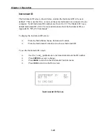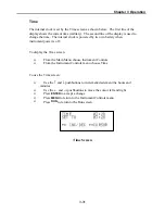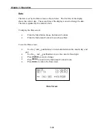
Chapter 3 Operation
3-17
CO Background Correction
The CO background correction is determined during zero calibration. The CO
background is the amount of signal read by the analyzer while sampling zero air. The
background signal is electrical noise. Before the analyzer sets the CO reading to zero, it
stores the value as the CO background correction.
The CO Background screen is used to perform a manual zero calibration of the
instrument. As such, the instrument should sample zero air until stable readings are
obtained. The first line of the display shows the current CO reading. This reading is the
CO background signal. The second line of the display shows the CO background
correction that is stored in memory and is being used to correct the CO reading. That is,
the CO background correction is subtracted from the CO reading.
In the example below, the analyzer is reading 1.4 ppm of CO while sampling zero air.
The CO background correction is 0.0 ppm. That is, the analyzer is not applying a zero
background correction. The question mark is used as a prompt to change the background
correction. In this case the background correction must be increased to 1.4 ppm in order
for the CO reading to be at 0 ppb.
To set the CO reading in the example below to zero, use the
↑
pushbutton to increment
the CO background correction to 1.4 ppm. As the CO background correction reading is
increased, the CO reading is decreased. At this point however, no real changes have been
made. The analog outputs have not been affected and the stored CO background
correction of 0.0 ppm is still being used. Press the
ENTER
pushbutton to set the CO
reading to 0 ppm and store the background correction of 1.4 ppm. To escape without
making any changes, press the
MENU
pushbutton to return to the Calibration Factors
menu or the
RUN
pushbutton to return to the Run screen.
Содержание 48C
Страница 4: ......
Страница 12: ......
Страница 14: ......
Страница 18: ......
Страница 27: ...Chapter 3 Operation 3 3 Figure 3 2 Flowchart of Menu Driven Software ...
Страница 112: ......
Страница 116: ......
Страница 120: ......
Страница 123: ...Chapter 7 Servicing 7 3 Figure 7 2 Model 48C Component Layout 48P737 ...
Страница 125: ...Chapter 7 Servicing 7 5 Figure 7 3 Optical Bench Exploded View 42P761 ...
Страница 138: ......
Страница 146: ...Chapter 9 Optional Equipment 9 2 Figure 9 2 Model 48C Dimensional Outline D42P725 ...
Страница 155: ...Chapter 9 Optional Equipment Figure 9 8 Purge Housing Assembly 9 11 ...
Страница 158: ......
Страница 178: ...Appendix B RS 232 Commands B 20 µ ...
Страница 184: ......
Страница 186: ...C 2 ...
Страница 187: ...C 3 ...
Страница 188: ...C 4 ...
Страница 189: ...C 5 ...
Страница 190: ...C 6 ...
Страница 191: ...C 7 ...
Страница 192: ...C 8 ...
Страница 193: ...C 9 ...
Страница 194: ...C 10 ...
Страница 195: ...C 11 ...
Страница 196: ...C 12 ...
Страница 197: ...C 13 ...
Страница 198: ...C 14 ...
Страница 199: ...C 15 ...
Страница 200: ......
Страница 201: ...APPENDIX D PUMP MAINTENANCE ...
Страница 202: ......
Страница 203: ......
Страница 204: ......


