xi
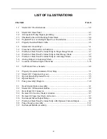
LIST OF ILLUSTRATIONS
FIGURE PAGE
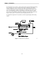
1-1
Model 48C Flow Schematic................................................................................. 1-2
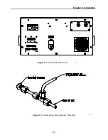
2-1
Model 48C Rear Panel ......................................................................................... 2-3
2-2
Atmospheric Dump Bypass plumbing ................................................................. 2-3
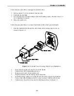
2-3
Shielded Cable with Shielding Pulled Back ........................................................ 2-4
2-4
Exploded View of Analog Output Cover Installation.......................................... 2-5
2-5
Properly Installed Shield Cable............................................................................ 2-6
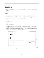
3-1
Model 48C Front Panel........................................................................................ 3-1
3-2
Flowchart of Menu-Driven Software................................................................... 3-3
3-3
Pin-Out of Rear Panel Terminal Strip in Single Range Mode............................. 3-7
3-4
Pin-Out of Rear Panel Terminal Strip in Dual Range Mode ............................... 3-7
3-5
Pin-Out of Rear Panel Terminal Strip in Autorange Mode ................................. 3-8
3-6
Analog Output in Autorange Mode ..................................................................... 3-9
3-7
Location of Internal Option Switches ................................................................ 3-76
4-1
Calibration Flow schematic ................................................................................. 4-4
7-1
Properly Grounded Antistatic Wrist Strap ........................................................... 7-1
7-2
Model 48C Component Layout............................................................................ 7-3
7-3
Optical Bench (Exploded View).......................................................................... 7-5
7-4
Optical Bench....................................................................................................... 7-7
7-5
Pump Assembly Diagram .................................................................................. 7-10
9-1
Rack Mount Option Assembly............................................................................. 9-1
9-2
Model 48C Dimensional Outline......................................................................... 9-2
9-3
Rear Panel I/O Connector .................................................................................... 9-6
9-4
Remote I/O Zero Gas Mode Activation............................................................... 9-7
9-5
Remote I/O Span Gas Mode Activation .............................................................. 9-7
9-6
Instrument Status Output Relays.......................................................................... 9-8
9-7
Pin-Out of Rear Panel Terminal Strip with Optional Current Output ................. 9-9
9-8
Purge Housing Assembly................................................................................... 9-11
9-9
Instrument Handle Assembly............................................................................. 9-12
Содержание 48C
Страница 4: ......
Страница 12: ......
Страница 14: ......
Страница 18: ......
Страница 27: ...Chapter 3 Operation 3 3 Figure 3 2 Flowchart of Menu Driven Software ...
Страница 112: ......
Страница 116: ......
Страница 120: ......
Страница 123: ...Chapter 7 Servicing 7 3 Figure 7 2 Model 48C Component Layout 48P737 ...
Страница 125: ...Chapter 7 Servicing 7 5 Figure 7 3 Optical Bench Exploded View 42P761 ...
Страница 138: ......
Страница 146: ...Chapter 9 Optional Equipment 9 2 Figure 9 2 Model 48C Dimensional Outline D42P725 ...
Страница 155: ...Chapter 9 Optional Equipment Figure 9 8 Purge Housing Assembly 9 11 ...
Страница 158: ......
Страница 178: ...Appendix B RS 232 Commands B 20 µ ...
Страница 184: ......
Страница 186: ...C 2 ...
Страница 187: ...C 3 ...
Страница 188: ...C 4 ...
Страница 189: ...C 5 ...
Страница 190: ...C 6 ...
Страница 191: ...C 7 ...
Страница 192: ...C 8 ...
Страница 193: ...C 9 ...
Страница 194: ...C 10 ...
Страница 195: ...C 11 ...
Страница 196: ...C 12 ...
Страница 197: ...C 13 ...
Страница 198: ...C 14 ...
Страница 199: ...C 15 ...
Страница 200: ......
Страница 201: ...APPENDIX D PUMP MAINTENANCE ...
Страница 202: ......
Страница 203: ......
Страница 204: ......


