22
4. Use thread joint compound resistant to the action of
liquefied petroleum gas.
WARNING
Failure to use proper thread compounds on all
gas connectors may result in leaks of flammable
gas.
5. All above ground gas piping upstream from field
supplied manual gas valve must be electrically
continuous and bonded to a grounding electrode.
Do not use gas piping as grounding electrode. Refer
to National Electrical Code, ANSI/NFPA 70 and /or
CSA C22.1 Electrical Codes.
WARNING
Gas supply to boiler and system must be
absolutely shut off prior to installing or servicing
boiler gas piping.
WARNING
Use an additional gas pressure regulator where
the gas pressure is greater than 5 psig. Using
one additional regulator for multiple boilers
may result in unsafe boiler operation. The
additional regulator must be able to properly
regulate gas pressure flow at the lowest input
of a single boiler. If the regulator cannot do this,
two or more additional regulators are required.
Consult regulator manufacturer's instructions for
minimum gas flow rate.
6. Pressure test. The boiler and its gas connection
must be leak tested before placing boiler in
operation.
a. Protect boiler gas control valve. For all testing
over ½ psig, boiler and its individual shutoff
valve must be disconnected from gas supply
piping. For testing at ½ psig or less, isolate
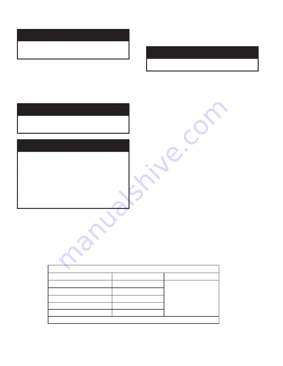
TABLE 3 - BOILER GAS TRAIN INLET PRESSURE
Boiler Model
MIN. ("w.c.)
MAX.
EVO-500
5.0
5 psi-NG
2 psi-LP
EVO-750*
7.0
EVO-1000*
7.0
EVO-1500*
7.0
EVO-2000*
9.0
* Available with optional gas train with min 4" w.c. inlet gas pressure.
boiler from gas supply piping by closing the
boiler's individual manual shutoff valve.
b. Locate leaks using approved combustible
gas detector, soap and water, or similar
nonflammable solution.
DANGER
Do not use matches, candles, open flames or
other ignition source to check for leaks.
Содержание EVO-1000
Страница 12: ...12 Figure 3 Sidewall Positive Pressure Venting Optional Figure 2 Sidewall Positive Pressure Venting...
Страница 13: ...13 Figure 4 Vertical Pressurized Venting...
Страница 15: ...15 Figure 5 Typical Negative Pressure Conventional Venting...
Страница 17: ...17 Figure 7 Vertical Air Intake Piping...
Страница 26: ...26 Figure 9a Standard UL FM CSD 1 Wiring Diagram on off EVO 500 2000...
Страница 27: ...27 Figure 9b Standard UL FM CSD 1 Wiring Diagram Modulation EVO 500 2000...
Страница 30: ...30 Figure 11 Modular System Horizontal Air Intake Piping...
Страница 31: ...31 Figure 12 Modular System Vertical Air Intake Piping...
Страница 32: ...32 Figure 13 Modular System Typical One Pipe Water Piping...
Страница 33: ...33 Figure 14 Modular System Typical Primary Secondary Water Piping...
Страница 34: ...34 Figure 15 Modular System Typical Primary Secondary without System Pump...
Страница 35: ...35 Figure 16 Modular System Typical Reverse Return Water Piping...
Страница 36: ...36 Figure 17 Modular System Reverse Return with System Pump Only...
Страница 37: ...37 Figure 18 Modular System Typical Primary Secondary with Reverse Return...
Страница 47: ...47 This Page Intentionally Left Blank...
Страница 48: ...48 Troubleshooting Guide B Troubleshooting Guide...
Страница 49: ...49 Troubleshooting Guide...
Страница 53: ...53 This Page Intentionally Left Blank...
Страница 54: ...54 Figure 19 Combustion Chamber Assembly...
Страница 56: ...56 Figure 20 Burner Assembly FRONT VIEW TOP VIEW...
Страница 58: ...58 Figure 21 UL FM CSD 1 Main Gas Train Assembly...
Страница 60: ...60 Figure 22a DB B DB B w POC Gas Train 500 750 Figure 22b DB B DB B w POC Gas Train 1000 2000...
Страница 62: ...62 Figure 23 Jacket Panels 4D 4J 4C 4B 4F 4I 4G 4E 4R 4K 4H 4J 4N 4M 4L 4Q 4A 4P 4P...
Страница 64: ...64 Figure 24a Control Panel Assembly On Off...
Страница 66: ...66 Figure 24b Control Panel Assembly Modulation...
Страница 68: ...68 Figure 25 Bishop Pilot Assembly...
Страница 72: ...72 NOTES...
Страница 73: ...73 NOTES...
Страница 74: ...74 NOTES...
Страница 75: ...75 NOTES...


