16
B.
COMBUSTION AIR -
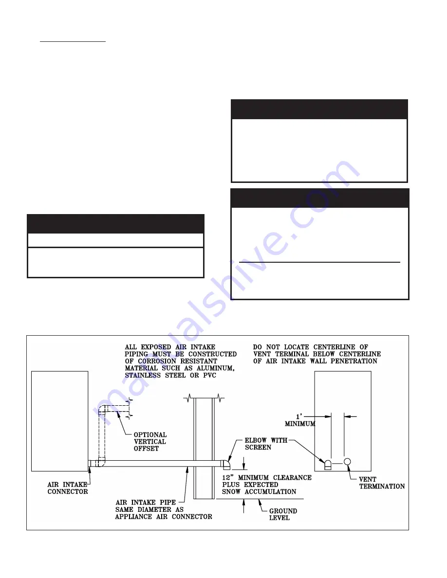
See Figures 6 and 7.
1. The boiler may be operated with inside or outside
air.
2. Refer to air intake piping drawings in this section
for proper outside air installation details.
3. Combustion air conduit can be galvanized smoke
pipe, PVC, CPVC, or flexible aluminum conduit.
4. The maximum air intake pipe length is fifty (50)
equivalent feet. Air intake pipe length is equal to
the total length of straight pipe plus the equivalent
length of fittings. Consult intake pipe manufacturer
for equivalent length of fittings and pipe.
5. Consult air intake pipe manufacturer's instructions
for proper method of sealing vent pipe sections
and fittings. Do not use other adhesives or sealants
except as expressly permitted by the vent pipe
manufacturer's instructions.
WARNING
Do not reduce size of air intake pipe.
Read, understand and follow combustion air
instruction restrictions contained in the Pre-
Installation instructions of this manual.
6. Air intake termination must be located at least
twelve (12) inches above grade plus the expected
snow accumulation.
Figure 6: Horizontal Air Intake Piping
7. Boiler may be installed with vertical venting and
sidewall intake air or visa versa.
8. The horizontal air intake pipe must be adequately
supported with straps or supports no less than five
(5) feet apart. The completed air intake pipe system
must be rigid and able to withstand impacts without
collapse.
CAUTION
Dirty, contaminated or dusty air used for
combustion will decrease the useful life of
the boiler air filter. Use outside air if inside
air quality is questionable. Use outside air if
the boiler is installed in manufacturing plants,
laundries, dry cleaners or other locations with
heavy particulates in the air.
WARNING
Do not locate air intake where petroleum
distillates, CFCs, detergents, volatile vapors
or any other chemicals are present. Severe
boiler corrosion and failure will result.
Thermal Solutions does not warrant failures
caused by contaminated air.
Do not locate air intake termination where
natural convection or wind conditions may
cause the boiler exhaust gases to be drawn
into the air intake.
Содержание EVO-1000
Страница 12: ...12 Figure 3 Sidewall Positive Pressure Venting Optional Figure 2 Sidewall Positive Pressure Venting...
Страница 13: ...13 Figure 4 Vertical Pressurized Venting...
Страница 15: ...15 Figure 5 Typical Negative Pressure Conventional Venting...
Страница 17: ...17 Figure 7 Vertical Air Intake Piping...
Страница 26: ...26 Figure 9a Standard UL FM CSD 1 Wiring Diagram on off EVO 500 2000...
Страница 27: ...27 Figure 9b Standard UL FM CSD 1 Wiring Diagram Modulation EVO 500 2000...
Страница 30: ...30 Figure 11 Modular System Horizontal Air Intake Piping...
Страница 31: ...31 Figure 12 Modular System Vertical Air Intake Piping...
Страница 32: ...32 Figure 13 Modular System Typical One Pipe Water Piping...
Страница 33: ...33 Figure 14 Modular System Typical Primary Secondary Water Piping...
Страница 34: ...34 Figure 15 Modular System Typical Primary Secondary without System Pump...
Страница 35: ...35 Figure 16 Modular System Typical Reverse Return Water Piping...
Страница 36: ...36 Figure 17 Modular System Reverse Return with System Pump Only...
Страница 37: ...37 Figure 18 Modular System Typical Primary Secondary with Reverse Return...
Страница 47: ...47 This Page Intentionally Left Blank...
Страница 48: ...48 Troubleshooting Guide B Troubleshooting Guide...
Страница 49: ...49 Troubleshooting Guide...
Страница 53: ...53 This Page Intentionally Left Blank...
Страница 54: ...54 Figure 19 Combustion Chamber Assembly...
Страница 56: ...56 Figure 20 Burner Assembly FRONT VIEW TOP VIEW...
Страница 58: ...58 Figure 21 UL FM CSD 1 Main Gas Train Assembly...
Страница 60: ...60 Figure 22a DB B DB B w POC Gas Train 500 750 Figure 22b DB B DB B w POC Gas Train 1000 2000...
Страница 62: ...62 Figure 23 Jacket Panels 4D 4J 4C 4B 4F 4I 4G 4E 4R 4K 4H 4J 4N 4M 4L 4Q 4A 4P 4P...
Страница 64: ...64 Figure 24a Control Panel Assembly On Off...
Страница 66: ...66 Figure 24b Control Panel Assembly Modulation...
Страница 68: ...68 Figure 25 Bishop Pilot Assembly...
Страница 72: ...72 NOTES...
Страница 73: ...73 NOTES...
Страница 74: ...74 NOTES...
Страница 75: ...75 NOTES...


