70
A. Description
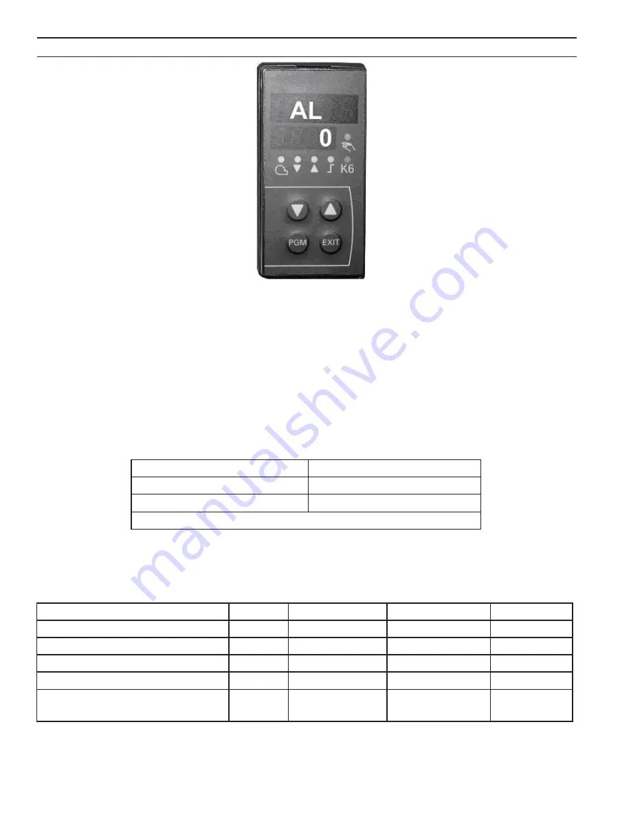
The microprocessor based temperature controller is utilized for all modulating Thermal Solutions water boilers. The basic
function of the controller is to modulate the firing rate of the burner in response to the boiler heat load. The controller monitors
the boiler water temperature through the use of a sensor located in the boiler pressure vessel. The controller compares the boiler
water temperature to the controller’s user defined operating set-point temperature.
An output signal from the microprocessor varies the blower speed through the use of a variable frequency drive (VFD). The gas
valve regulates an appropriate amount of gas flow for a given air flow or blower speed. The user may adjust the operating set-
point temperature for a given application. In addition, the controller has the ability to change to an alternate set-point through an
external signal for low load conditions (i.e. weekend use, night setback). Outdoor reset is another standard feature, allowing the
boiler operating temperature to vary based on the outdoor ambient temperature. The typical result is a higher seasonal efficiency.
Other features include:
B. Set-Up
All of the control parameters have been set at the factory. There are a few parameters called “Process Parameters” that must be
defined by a qualified operator. The table below will help serve as a reference and record when making adjustments.
Low Fire Hold
Multiple Analog Inputs
Multiple Set Points
Mod Bus Communications
Digital Inputs
Manual Overrive
"AUTO TUNE" Optimization
Parameter
Display
Value Range* Factory Setting User Setting
Setpoint 1
SP1
145-240
180
Setpoint 2
SP2
145-240
0
Digital Setpoint Shift (optional)
dSP
145-240
0
Outside Temperature (optional)
TA
Consult Factory
—
Pre-definition of External
Sepoints (optional)
SP.E
Consult Factory
—
IX. Temperature Controller Operation for Modulating Boilers
Setpoint Value
Burner On
Decrease Value
Содержание EVO-1000
Страница 12: ...12 Figure 3 Sidewall Positive Pressure Venting Optional Figure 2 Sidewall Positive Pressure Venting...
Страница 13: ...13 Figure 4 Vertical Pressurized Venting...
Страница 15: ...15 Figure 5 Typical Negative Pressure Conventional Venting...
Страница 17: ...17 Figure 7 Vertical Air Intake Piping...
Страница 26: ...26 Figure 9a Standard UL FM CSD 1 Wiring Diagram on off EVO 500 2000...
Страница 27: ...27 Figure 9b Standard UL FM CSD 1 Wiring Diagram Modulation EVO 500 2000...
Страница 30: ...30 Figure 11 Modular System Horizontal Air Intake Piping...
Страница 31: ...31 Figure 12 Modular System Vertical Air Intake Piping...
Страница 32: ...32 Figure 13 Modular System Typical One Pipe Water Piping...
Страница 33: ...33 Figure 14 Modular System Typical Primary Secondary Water Piping...
Страница 34: ...34 Figure 15 Modular System Typical Primary Secondary without System Pump...
Страница 35: ...35 Figure 16 Modular System Typical Reverse Return Water Piping...
Страница 36: ...36 Figure 17 Modular System Reverse Return with System Pump Only...
Страница 37: ...37 Figure 18 Modular System Typical Primary Secondary with Reverse Return...
Страница 47: ...47 This Page Intentionally Left Blank...
Страница 48: ...48 Troubleshooting Guide B Troubleshooting Guide...
Страница 49: ...49 Troubleshooting Guide...
Страница 53: ...53 This Page Intentionally Left Blank...
Страница 54: ...54 Figure 19 Combustion Chamber Assembly...
Страница 56: ...56 Figure 20 Burner Assembly FRONT VIEW TOP VIEW...
Страница 58: ...58 Figure 21 UL FM CSD 1 Main Gas Train Assembly...
Страница 60: ...60 Figure 22a DB B DB B w POC Gas Train 500 750 Figure 22b DB B DB B w POC Gas Train 1000 2000...
Страница 62: ...62 Figure 23 Jacket Panels 4D 4J 4C 4B 4F 4I 4G 4E 4R 4K 4H 4J 4N 4M 4L 4Q 4A 4P 4P...
Страница 64: ...64 Figure 24a Control Panel Assembly On Off...
Страница 66: ...66 Figure 24b Control Panel Assembly Modulation...
Страница 68: ...68 Figure 25 Bishop Pilot Assembly...
Страница 72: ...72 NOTES...
Страница 73: ...73 NOTES...
Страница 74: ...74 NOTES...
Страница 75: ...75 NOTES...


