


DVOR 432
Operation and Maintenance
Repairs
6-17
Ed. 01.04
6.2.3
Replacing Subassemblies
WARNING
The heat sinks of the modulators (MOD-110P) and of the carrier amplifier (CA-100C)
may warm up during operation. This is normal and does not affect the function. When reĆ
placing these subassemblies it is recommended to let them cool down for a while or take
suitable measures (e.g. gloves). When replacing the subassemblies SYN und CCP avoid
touching the heat sinks of the MOD-110P.
6.2.3.1
Disconnecting the Voltage before replacing Subassemblies
CAUTION
The voltage must always be disconnected before removing or installing subassemblies
(subject to only a very few exceptions). It is sufficient to switch off all the transmitter subasĆ
semblies, the DCC-MV and the DCC-28 with either of switches TX1 or TX2 on the PMM
subassembly. The transmitter subassemblies can also be switched off by means of a PC
command.
Before replacing an ACC-module the BCPS must always be disconnected from the
mains.
If a monitor subassembly is affected (MSP-VD), the associated DCC subassemblies
must be removed. It is not necessary to switch them off beforehand with both TX1 and
TX2 on the PMM.
If the CSL must be changed, both TX1
and
TX2 must be switched off beforehand.
The VAM, MODEM and the DCC-3-05 subassemblies may be removed and installed
when live. The special design of their contacts prevents damage from occurring.
6.2.3.2
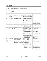
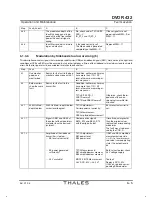
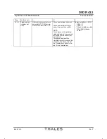
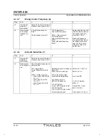
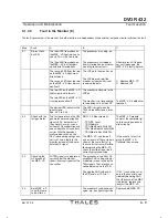
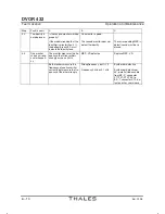
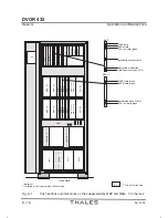
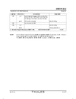
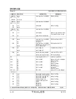
Subassemblies in the Transmitter Rack and Power Supply
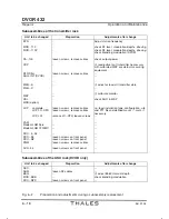
The table below lists the work which may be necessary after a subassembly has been replaced.
Please also refer to Sections 6.2.1.1 and 6.2.1.1.3 .
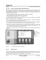
a) The relevant transmitter must be de-energized before removing or installing subassemblies, prefĆ
erably by switching it off on the PMM subassembly. It should be noted that the following subassemĆ
blies are only de-energized if both switches and switch NAV (for CSL) on the PMM are switched
off:
LCP
DCC-3-05
CSL
MSP-VD
VAM
ASU complete (DVOR only)
b) Several of the subassemblies have DIP-FIX switches or jumpers on their pc boards. It is essential
to check that the switches or jumpers on the new subassemblies are set to the same positions as
on the old subassemblies. Section 6.2.4 contains a list of the DIP-FIX switches and jumpers.
c) Check that all the RF cables have been connected correctly before switching the transmitter on
again, and make sure that either the antenna or a dummy load is connected to the transmitter
output signals (CSB, SB1, SB2).
d) All subassemblies in the assembly carrier have plug-in RF connections.
Содержание DVOR 432
Страница 2: ......
Страница 4: ......
Страница 16: ...DVOR 432 Table of Contents Operation and Maintenance X Ed 01 04 ...
Страница 38: ...DVOR 432 General Information Operation and Maintenance 1 6 Ed 01 04 ...
Страница 40: ...DVOR 432 General Information Operation and Maintenance 1 8 Ed 01 04 ...
Страница 46: ......
Страница 66: ...DVOR 432 Installation Operation and Maintenance 2 24 Ed 01 04 ...
Страница 74: ......
Страница 136: ...DVOR 432 Installation Operation and Maintenance 4 32 Ed 01 04 ...
Страница 172: ...DVOR 432 Repairs Operation and Maintenance 6 22 Ed 01 04 ...
Страница 186: ...DVOR 432 Repairs Operation and Maintenance 6 36 Ed 01 04 ...
Страница 192: ...DVOR 432 Installation Operation and Maintenance Annex Nextfield AN 4 Ed 01 04 ...
Страница 194: ......
Страница 195: ...DVOR 432 Operation and Maintenance Annex Nextfield L 1 Ed 01 04 CHAPTER 2 CHAPTER 3 For Chapter numbering only ...
Страница 196: ...DVOR 432 General Operation and Maintenance Annex Nextfield L 2 Ed 01 04 ...
Страница 204: ...DVOR 432 Alignment Procedure Operation and Maintenance Annex Nextfield AN 14 Ed 01 04 ...
Страница 234: ...DVOR 432 Maintenance Operation and Maintenance Annex Nextfield AN 44 Ed 01 04 ...