


DVOR 432
Operation and Maintenance
Fault Location
6-3
Ed. 01.04
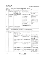
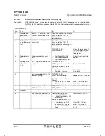
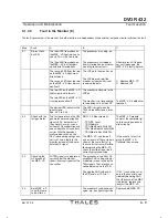
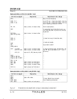
6.1.3.4
RF-Level too low or missing (3)
* 100 W version only
Step
Fault
A
B
C
3.1
One monitor
good, one moĆ
nitor bad
Fault in the monitor dipole
Fault in the HF cable from
monitor dipole to transmitter
Search for the fault in the
bad monitor and continue
with 8.1.
3.2
Bothmonitors
show the same
fault.
Search for the fault in the line
frommonitor dipole to transĆ
mitter or in the transmitter.
3.2.1
Antenna or
cabledefective.
Measure the leading HF sigĆ
nal at the transmitter output.
Check the returning signal at
the transmitter output.
TX1/2 BITE ADC-1: ACA1
TX1/2 BITE ADC-1: ACA1R
normal? Otherwise, check the
impedance of the transmitter's
termination.
If the rated value is good,
examine the monitor. If the
signal is too low, search
for the fault in the transmitĆ
ter.
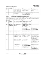
3.2.2
Transmitter inĆ
correctlyset.
CSB power correctly set?
TX1/2-Adjustm.CSB-Power? The nominal value should
be set here.
3.2.3
Transmitter RF
power off?
CSB power switched off via
the control bit?
TX1/2 BITE Digital:
CSB-Power State?
CSB-Power State must
be ON.
3.2.4
Supply voltage
for HF section?
One or several supply voltĆ
ages considerably below the
minimum?
MON1/2 BITE Measurement:
DCC-MV TX1/2 (+28 V)
supplies the modulators.
TX1/2-BITE ADC-2: V281
(+28 V) supplies CA-100*.
Nominal voltage ±5 %; in
the event of a fault, reĆ
place the power supply,
DCC-MV or DCC-28.
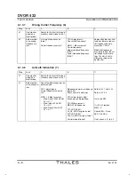
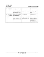
3.2.5.1 Synthesizer
Synthesizeroperatingoutside
of the frequency range from
108 to 118MHz
MON1/2 Measurement:
Carrier Frequency?
Both monitors show a freĆ
quency error.
Only one monitor shows a freĆ
quency error.
Replace the synthesizer.
Replace corr. MSP-VD or
check cable; see 8.6, 8.7.
3.2.5.2 Synthesizer
Synthesizer HF output level
too low.
TX1/2 BITE Digital:
Synth. Level CSB-Signal?
Replace the synthesizer.
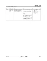
3.2.6
Switched off because the conĆ
trol loop has a discontinuity.
TX1/2 BITE Digital:
Loop Modulator CSB-1?
If yes, continue with
3.2.6.1.
3.2.6.1 Control loop of
thetransmitter
has a discontiĆ
nuity.
First set CSB=0 W.
Then set CSB=5 W or less.
RF-Level >50 %:
control loop open, thin HF
cable has come off CA-100,
or has been pressed out of
CCP-D,
Directional coupler in the
CA-100* defective or has a
discontinuity,
MOD 110 for CSB is defective
or CCP-D defective
- Check cable
- Check cable
- Replace CA-100*
- Replace MOD-110 for
CSB
- ReplaceCCP-D
3.2.6.2 Check ampliĆ
tudecontrol
loop.
First set CSB=0 W,
Then set CSB=0.1 P
nom
.
30 % < RF-Level <40 %
Control loop is good.
CA-100* only operating with
partial power.
Modulation depth at nomiĆ
nal power is reduced
ReplaceCA-100*.
3.2.7
Control signal fromthe
MSG-S is too low. Set the
transmitter'snominalpower.
TX1/2 BITE ADC2:
CSB_1S2, CSB_1_ST_6 at the
nominalvalue?
Substantially less than the
nominal value.
Replace the MSG-S
Содержание DVOR 432
Страница 2: ......
Страница 4: ......
Страница 16: ...DVOR 432 Table of Contents Operation and Maintenance X Ed 01 04 ...
Страница 38: ...DVOR 432 General Information Operation and Maintenance 1 6 Ed 01 04 ...
Страница 40: ...DVOR 432 General Information Operation and Maintenance 1 8 Ed 01 04 ...
Страница 46: ......
Страница 66: ...DVOR 432 Installation Operation and Maintenance 2 24 Ed 01 04 ...
Страница 74: ......
Страница 136: ...DVOR 432 Installation Operation and Maintenance 4 32 Ed 01 04 ...
Страница 172: ...DVOR 432 Repairs Operation and Maintenance 6 22 Ed 01 04 ...
Страница 186: ...DVOR 432 Repairs Operation and Maintenance 6 36 Ed 01 04 ...
Страница 192: ...DVOR 432 Installation Operation and Maintenance Annex Nextfield AN 4 Ed 01 04 ...
Страница 194: ......
Страница 195: ...DVOR 432 Operation and Maintenance Annex Nextfield L 1 Ed 01 04 CHAPTER 2 CHAPTER 3 For Chapter numbering only ...
Страница 196: ...DVOR 432 General Operation and Maintenance Annex Nextfield L 2 Ed 01 04 ...
Страница 204: ...DVOR 432 Alignment Procedure Operation and Maintenance Annex Nextfield AN 14 Ed 01 04 ...
Страница 234: ...DVOR 432 Maintenance Operation and Maintenance Annex Nextfield AN 44 Ed 01 04 ...