Quick Start Guide
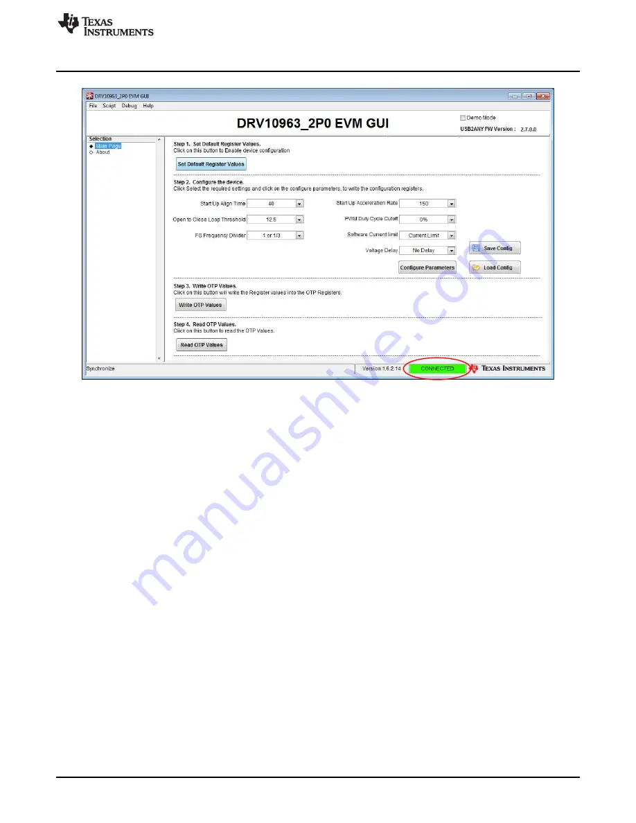
Figure 5. GUI Screen With Successful I2C Interface
3. Left-click on the step 1 button “Set Default Resister Values”. Step 1 is always mandatory before
proceeding to step 2 to enable configuration of the device. This step programs the following
parameters to the corresponding shadow register, as shown in
. These default values
correspond to the factory programmed part DRV10963JJ. Refer to the DRV10963 datasheet for a
detailed explanation of different versions of DRV10963 and descriptions of tunable parameters.
•
"Start Up Align Time" - 350 ms and "Start-up Acceleration Rate" - 80 Hz/s
•
"Open to Close Loop Threshold" - 100 Hz
•
"PWM Duty Cycle Cutoff" - 10%
•
"FG Frequency Divider" - 1 or 1/3
•
"Software Current limit" - 500 mA
•
"Voltage Delay" - 120 µs
To enable motor spin with the above parameters, open the jumper J1 on the motherboard. There is a
high probability that the motor will start rotating with previously shown default values. This state is
equivalent to driving the motor at maximum speed with 100% duty cycle because PWM input being
connected to the I
2
C clock input continues to receive a high signal. Ensure that the parameters
previously shown are optimized for their end application. Refer to
for guidelines to optimally
determine and tune motor parameters using the GUI.
9
SLAU643 – July 2015
DRV10963 Evaluation Module
Copyright © 2015, Texas Instruments Incorporated


